
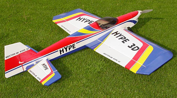
I recently acquired a Weston Hype 3D. It was brand new but with no box. I am not into 3D as such. No-one seemed to want it so I took it on as a general "muck about" plane and it would be a shame for it to go to the bin which it was destined to be. After doing some research for a manual or some kind of guide it appears that there is not much on the "Tube" for these things although there were a few items for the Mini Hype but scarcely anything for the 60+ inch version. I found a manual but it was for a later version as the one I was looking at did not have a battery hatch or EP conversion mount. Neither were any control wire guide tubes installed as per the manual. Oh No! What have I commited too?
The fuselage is very narrow at the cockpit to wing saddle. Other than some 1/4 balsa rail along the sides and one at top centre there is only the balsa skin to brace all this. This is gonna snap in half inevitably on hard landing! Very first job to fix. then. I cut some 3mm laser ply strips and glued these down each side between the Fomer F2 and F3. Also had to open up the wing dowel slot in F2 as appeared to incorrect.
Landing Gear Mod
The later version's manual does state that the landing gear mounting is subject to breaking out or splitting as it was very thin, the captured nuts would pull through and it was easily to see why. I did add an extra layer of ply as recommended but after a few flights the rolling resistance of grass it was obvious that the landing gear was tipping backwards. So, off came the cowl to gain access to the mounting. Removed the landing gear, pressed the mounting plate back down with lots of epoxy added. I made up two aluminium brackets from strip. They are fixed by screws at the front and the landing gear bolts down over them.
Power Train
I did not want to spend any money on it and I should have enough components in my gold mine of a Parts Store. The Hype has long tail so a fairly heavy motor may be need up front. Laying idle was an Eflite Power 60 400kv so that would fit the bill. I would need some aluminium stand-offs to get the drive washer clear of the cowl. These were made up for me by another club member so that was sorted. Unfortunately I mis-calculated the cowl position so had to use some slightly cut down DLE stand-offs. Speed Controller was a conundrum. I only had spare top of the range Hobbywing Platinum Pros. Too good for this thing and a waste! No choice but to buy one. An overkill with an 80 amp "Red Brick" from Hobbyking but cheap enough and popular. To mount this ESC I needed to make up a mounting plate under the motor and directly in the air flow. See images.....
Wings and Stabiliser
Control surfaces are secured by Mylar hinges, I did not like Weston's so used my own. Simple enough job to secure surfaces to wings with thin CA. The slot for the stabiliser had be to found under the film covering so a bit of probing was required and then remove the covering. the slot was a bit tight to slide the stabiliser in so a bit of hacking, i mean slicing needed with a scalpel until it slid through the fuselage with a tiny bit of resistance. With wing bolted on I could now check and align the stabiliser and once happy drop some thin CA all round. Surprisingly the stabiliser was level in fuselage slot! Now the elevator halves are dry aligned first and then secured to the stabiliser with thin CA at the Mylar hinges. Looking like a plane now!
Surface Controls
Now this is where the "fun" starts. The servo tray in the fuselage did not really look like the one in the manual. After some deliberation and wondering if I am wasting my time on this pile of junk I decided to make and fit whatever is necessary to mount servos, etc. First job was to make another servo tray for the rudder and the pre-made one in the fuselage can do the elevators. one of these servos would have sitting higher than the rearmost one so the wires don't tangle or interfere with each other.
With this completed I now had to make up a custom former with 6 off, 4mm holes aligned with the servo arms on each servo. By sheers guess work I used long length of wire to work out where the wires would likely exit the fuselage at the back for each control wire allowing also for them to cross-over inside. Once I figured the where they would exit I marked with a felt tip. The manual for the later version helped here as a guide to exits. Using craft knife and scalpel I slotted the fuselage sides. On the underside behind the former 3, I cut out the film covering to fit the new 6 hole former behind it and also so I could guide the plastic tubes from SLEC to exiting out at the correct slots. I cut the excess off tubing off but left enough for any adjustments later. With new former in place it was glued in with epoxy and the plastic tubes pushed back through it until they were just proud of the surface. Drops of epoxy here too. Moving back to the tubes at the tail I then cut off more excess leaving about 25mm proud of the fuselage. Where the film was cut out I created some lips at each end of the hole and then made a ply hatch which enables maintenance or repairs to made internally.
You have four wires for the elevators, two to pull up and two to pull down. These wires are fitted in pairs directly to the plastic servo arms mounted top and underside. The other end has adjusters and snap-links at the horns. The rudder is set up the same way with two wires for pull pull. The fitting of the wire and snap-links is done with the radio switched on. I used masking tape to hold the control surfaces in alignment then finalise the wired end and snap-link adjustment. Crimp and trim wire ends.
Battery
Now another fiddly job. Because of the design of the fuselage removing and fitting battery would require removal of the wing each time. I preferred this option as making a hatch on the top side of the fuselage would severely weaken the structure. A battery tray was made out of light ply where the fuel tank would have been. To support the front end of the tray I had to make a double lip for it to rest on and glue it to the firewall from the inside and avoid placing it over the stand-off screws on the inside. A bit fiddly but after a few dry runs I applied 4 minute epoxy, slid it into place and held it here by hand till epoxy set. 4 minutes seems a long time with out moving! The tray is now slid into place and will be supported at the other end by a rail glued across the fuselage and held with a screw. The empty unusable space above the battery is filled with a soft foam block to stop the battery “floating” upwards. Battery is also restrained with a strap. With the wing in place the battery cannot really move very far and I realised this quite early in the build and was concerned I may have trouble with the C of G. But as it turned out it was just about right with a Zippy 6 cell, 3000 mah Lipo weighing 410gms. Slots were created on the underside of the cowl to allow air to flow out after cooling the ESC.
In Flight
First flight I used a 15 x 8 APC – E prop and little trimming was required. After a 4 minutes of general test flying the the battery had only used 50 % of capacity. The Hype is not particularly fast (it was not designed to be) but will pull vertically easily and keep going and hold a 45 degree hover with no more than ¼ throttle with virtually no head wind. With the present lipo pack and prop I have had numerous flights and can get up to 10 to 12 mins of flight time using the throttle conservatively, in fact you don't really need much power to keep it flying. Power into the 15 x 8 prop is 850 watts which equates to 140 watts per lb working on the usual basis of 100 watts/lb. Elevator I used on low rates and aileron on low and high. High rates aileron and at speed it spins really quick so keep count of the turns. AUW All up weight is 6lbs 2 ozs.
Valuation
The big plank type wing is one piece and a pain to transport without care. The fuselage is long too with big control surfaces to add to the care side of things. Although that can be offset by the fun of hanging it around up the field. Hold it in a head wind with throttle and it just sits there going nowhere.
Update: 19th Sept 2020. I have now changed the prop to a 16 x12 APC – E and the power into the prop is in excess of 1150 watts at about 46 amps. Now 180 watts per lb.... Nearly 2 x power to weight ratio.

