- Posts: 3163
- Thank you received: 903
Weston Hype - Probably Was!
- Phil Ford
-
 Topic Author
- Offline
- Administrator
-

Less
More
5 years 2 months ago - 5 years 2 months ago #23092
by Phil Ford
Weston Hype - Probably Was! was created by Phil Ford
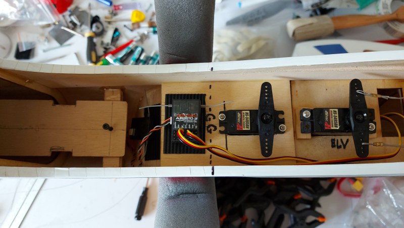
Recently I acquired this new unboxed kit to occupy myself during quiet times. I downloaded a copy of the manual and the images of the internals does not look like the thing sat on my "workshop" floor. After some thorough check ups I had come to believe this was a very early version at least 12 years I reckon. They were talking Futaba servos and NiCads! The slimmest part of the fuselage was central wing saddle and canopy. Um! A hard landing and it is gonna snap in half there without doubt. I have laid in some 4mm ply strips along this section to stiffen it up.
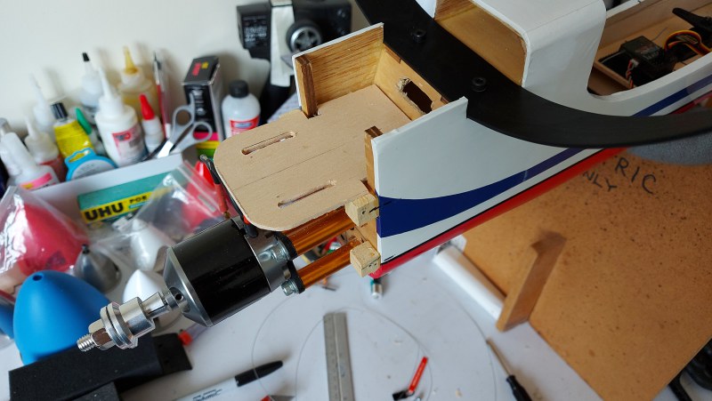
I had a Power 60 motor laying idle so after some measurements I needed some aluminium stand-offs. One of our members kindly made some up for me but found later I had not made some allowances (10mm in fact) for spinner clearance and how far back the cowl would go. So, I had to return to some DLE stand-offs and cut them down manually to the right length. (Hacksaw and file) Motor mounted! Not a lot of room for an ESC below the motor or where Weston suggest it go. Hence a new mounting plate directly in the airflow.
In their manual they show six tubes for the pull pull wires - not in this "thing" I got. Beginning to lose interest especially as other aircraft need some maintenance and am I wasting my time? Some time later returned to it again, mounted the wing so I could glue the stabiliser and fin post in. With that done I am wondering the likely position of the battery will be with that heavy lump up front and about 100 gms of ESC and power cable. With the fin, stab and wing mounted I could now slide a 6 cell lipo into the tank area and see where the plane balances. This gave me an idea of where and how to fit a battery tray. Not a lot of movement area though.
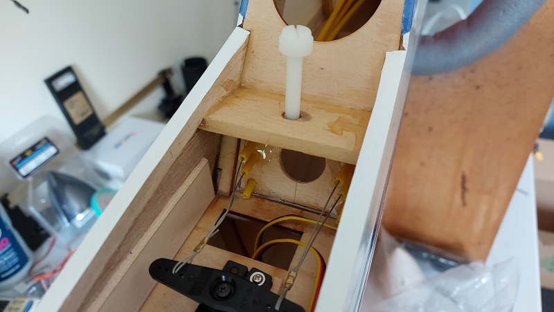
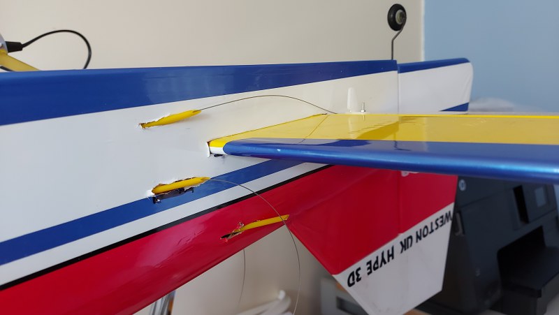
Ordered a shed load of SLEC plastic tubes for control wire guides. But how to install them. A lot of fiddling but made up a new sub-former at F3 drilled for the six 4mm tubes. Now the fun bit - where would the lines exit the fuselage. Studied the poor images of Weston's "manual" and using a long piece of wire and some imagination started hacking/slotting the fuselage. Had to cut a section of covering so I could get access the insid eof the fuselage. With that done time use the steel wire to guide the tubes to their exit points. Then slide the other ends through the new sub-former. Epoxy them at the former. Once cured them cut off excess tubes.
Last edit: 5 years 2 months ago by Phil Ford. Reason: Text errors
Please Log in or Create an account to join the conversation.
- Phil Ford
-
 Topic Author
- Offline
- Administrator
-

Less
More
- Posts: 3163
- Thank you received: 903
5 years 2 months ago #23093
by Phil Ford
Replied by Phil Ford on topic Weston Hype - Probably Was!
Today I have now fitted the pull wire into the tubes and connected to the servos. Now on hold waiting for some new 2mm snal clevises, 2mm wire adaptors as I am not happy with the supplied stuff. The kit's screws and wire adaptors are not metric either!
Found some talk about his Hype 60 size in forums from 20 years a go and they were not impressed them either. Some said theirs fell apart in the air!
Found some talk about his Hype 60 size in forums from 20 years a go and they were not impressed them either. Some said theirs fell apart in the air!
Please Log in or Create an account to join the conversation.
- Phil Ford
-
 Topic Author
- Offline
- Administrator
-

Less
More
- Posts: 3163
- Thank you received: 903
5 years 1 month ago - 5 years 1 month ago #23104
by Phil Ford
Replied by Phil Ford on topic Weston Hype - Probably Was!
Wing now has it's servos fitted and connected to the ailerons. Landing gear fitted. Pull pull bits did not come to today so can't connect the wires yet. On the good side HK's delivery came this morning with a juicy Turnigy Plush 32 80 amp ESC. I did have a Hobbywing 100 amp Pro but that is too good for this thing and an Eflite 60 ex-Habu 2 which may not be man enough. Soldering ready and fitted all the necessary bullets and connectors and then rushed outside whilst the drizzle had stopped.
Ran it up on 6 cell Zippy with a APC-e 15x8 on the business end. Nigh on 1100 watts! I think that may be enough power. Total weight of Hype (wing and fuselage weighted separately and allowing for 4000 maH Lipo AUW) approx 6.6lbs. With the ESC now fitted I was able to finally fit the cowl after opening up some cooling vents
Ran it up on 6 cell Zippy with a APC-e 15x8 on the business end. Nigh on 1100 watts! I think that may be enough power. Total weight of Hype (wing and fuselage weighted separately and allowing for 4000 maH Lipo AUW) approx 6.6lbs. With the ESC now fitted I was able to finally fit the cowl after opening up some cooling vents
Last edit: 5 years 1 month ago by Phil Ford.
Please Log in or Create an account to join the conversation.
Moderators: DaveBright
Time to create page: 0.234 seconds
Latest Posts
-
-

- Various Gliders from Dave Ambrose ex W.M.A.C Membe...
- In WimborneMac Members / For Sale - Exchange - Wanted
- by 4Pedalsfly
- 1 week 1 day ago
-
-
-

- Ray Ivey's Models
- In WimborneMac Members / For Sale - Exchange - Wanted
- by Phil Ford
- 2 weeks 7 hours ago
-
©
2009 - 2025
WMAC PCF Design


