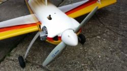
If you have read the previous article on the Wots Wot you will have read that this was the electric version. The basic model comes without any mounting kit. You select the which kit you wish to use, i.e.; electric or glow. In the previous article I built my Wots Wot for electric using a SK3 5045, 660 kV motor. The plane flew very nicely but I needed a that size motor for another project, and as much as I hate to "cannibalise" working models the motor had to come out. not wanting a machine that does not fly I decided that a biplane such as this really needs a nice four stroke glow. The following article describes the conversion back to glow, the opposite to what many do nowadays.
So I settled for an ASP80 from Just Engines which when run in would generate the same or better power than the SK3 Turnigy 5045 motor. Add to that the nice unrushed sound of a four stroke and you have an appealing biplane on the ground and in the air.
First job was to remove the motor and ESC followed by aluminium motor mounting plate and stand-offs. My battery carrier was located by screws at the front and as per the manual within the fuselage. The carrier was removed leaving just the carrier guide which is also part of the wing support above. The magnetic hatch was kept but the piece of ply that came with the electric kit with magnets was carefully cut away from the fuselage. This would be replaced with more sturdier ply so that the hatch can be located more securely because behind it will be the receiver battery, a 2800 4.8v eneloop pack which in my case was originally under the main battery carrier.
The IC kit comes with the engine bearers, tank and required nuts and bolts. The bearers are positioned using the screws provided using the same holes that the electric kit stand-offs used. This also sets the thrust angles too. The engine is then positioned so that the prop drive face is just clear of the cowl. Once happy, I then drilled four 3.5 mm holes in the engine mounting and used the 3mm bolts and nyloc nuts to secure.
The IC kit comes with a small tank, I had tried using a small Dubro but Ripmax seem to have made the formers to take their tank only! We are only talking a few millimetres but any cutting out would be rather trying and difficult now the air frame is assembled. The supplied tank is a neat slidng fit but strangely sits at a little angle sideways when the stopper is located in the firewall. Plumb in the lines as per usual. Used a second hand Futaba 3003 for the throttle and locates in an empty slot on the servo tray. I did not use the throttle wire and tube supplied but made up a throttle linkage using Sullivan snake with 2mm clevises each end to make minute adjustments.
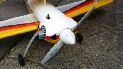
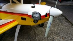
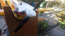
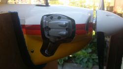
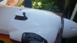
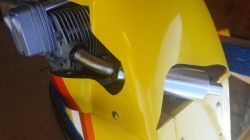
My favourite bit now, cutting the cowl to allow for the cylinder head, main jet and exhaust. I used some cardboard to mark where the centre of the rocker cover sits and transferred this to the cowl with a marker pen. then using a cutting disc made a small square hole. Then kept placing the cowl on the engine, making a note of where it is fouling and cut out a bit more. As the cowl begins to clear the cylinder head I then marked where the main jet will sit and again made some marks and cut out a slot a bit at a time. Finally after some gentle and careful sanding the cowl fits neatly over the engine.
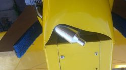
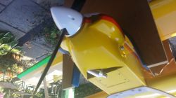
Time to make provision for the exhaust in the cowl. Unlike the image in the manual (image right) I did not want it sticking out ruining the lines of the aircraft. So I positioned the exhaust so it points down at an angle and exits nearly central underneath close to the firewall. Then pushing the cowl on and marking roughly where the cowl fouls the exhaust. Cutting a little bit at a time until the cowl clears the exhaust. There is not much of the power plant outside the cowl except for the cylinder head so a neat installation. Hot air exiting due to the shape of the cowl has plenty of space underneath to exit. In practice and after a few flights the exhaust residue does appear on the starboard lower wing surface and front underside of the fuselage. An exhaust deflector will reduce this some what.
The hatch was secured by four 3mm ply tabs glued on the underside of the aperture. To the hatch itself I made up a piece of ply that would fill in the space between the hatch and the fuselage therefore closing off the fuselage. This was glued to the hatch with epoxy.
Through the hatch area we can now see the tank and on top this I was going to install the flight pack directly under the hatch. I used foam packing trimmed enough to take the battery pack and placed this on top the tank. Another piece of foam, with a recess made to fit over the battery pack then was placed on top although it was a push fit to go inside the fuselage. Therefore when the hatch is screwed down the foam is slightly compressed and holds the pack securely. The battery lead then goes to a heavy duty switch/charge point and on my model this switch also has a led to remind it is On or Off and then on to the receiver.
Now with everything in place except for the cowl I rechecked the C of G. A bit tail heavy now but a 55 gram (2 oz) piece of lead siliconed and cable tied to the top engine beam did the trick. Refit cowl.
I was a little concerned about flight time on the smallish tank but was pleased that after 10 mins of reasonable flying/throttle there was still just under half a tank of fuel left, so economical too! Prop is a Xoar 14 x 6 at present but may try a bit more pitch for more speed but I prefer pulling power to speed especially with a biplane.
A number of flights now and climbs vertical for some distance with no issues. Speed about the same as the electric motor but the plodding sound of the four stroke music to my ears. I'll put up with cleaning off the oil.
Update: Pro is now an APC 14 x 6. No noticeable change in performance.

