- Posts: 3156
- Thank you received: 903

Aero Navigation Lights
- Phil Ford
-
 Topic Author
- Offline
- Moderator
-

Less
More
01 Feb 2017 19:35 #11809
by Phil Ford
Replied by Phil Ford on topic Aero Navigation Lights
Okay Okay! I've been hijacked so you have asked for it.  I thought it may have been of interest to some of you as this circuitry/module is far superior to the crap HK and others led systems. Read on if you wish.
The Darlington transistor (often called a Darlington pair) is a compound structure consisting of two bipolar transistors (either integrated or separated devices) connected in such a way that the current amplified by the first transistor is amplified further by the second one. This configuration gives a much higher current gain than each transistor taken separately and, in the case of integrated devices, can take less space than two individual transistors because they can use a shared collector. Integrated Darlington pairs come packaged singly in transistor-like packages or as an array of devices (usually eight) in an integrated circuit.
The Darlington configuration was invented by Bell Laboratories engineer Sidney Darlington in 1953. He patented the invention of having two or three transistors on a single chip sharing a collector. A similar configuration but with transistors of opposite type (one NPN and one PNP) is the Sziklai pair, sometimes called the "complementary Darlington".

The Array is so called because the pairs of transistors are embedded into a chip therefore eliminating the need for rows and rows of transistors.
I thought it may have been of interest to some of you as this circuitry/module is far superior to the crap HK and others led systems. Read on if you wish.The Darlington transistor (often called a Darlington pair) is a compound structure consisting of two bipolar transistors (either integrated or separated devices) connected in such a way that the current amplified by the first transistor is amplified further by the second one. This configuration gives a much higher current gain than each transistor taken separately and, in the case of integrated devices, can take less space than two individual transistors because they can use a shared collector. Integrated Darlington pairs come packaged singly in transistor-like packages or as an array of devices (usually eight) in an integrated circuit.
The Darlington configuration was invented by Bell Laboratories engineer Sidney Darlington in 1953. He patented the invention of having two or three transistors on a single chip sharing a collector. A similar configuration but with transistors of opposite type (one NPN and one PNP) is the Sziklai pair, sometimes called the "complementary Darlington".
The Array is so called because the pairs of transistors are embedded into a chip therefore eliminating the need for rows and rows of transistors.
Please Log in or Create an account to join the conversation.
- JRI
-
- Offline
- Platinum Member
-

Less
More
- Posts: 502
- Thank you received: 108
02 Feb 2017 07:45 #11810
by JRI
Replied by JRI on topic Aero Navigation Lights
Hmmm back on track, your diagram shows a very unusual depiction of the circuitry of a darlington array Phil. The circuits shown imply a logical NOT gate with the output voltage pegged to no more than the forward voltage of a diode (i.e typically 0.6v).
I.e. if you drove the input of a gate to say 6V, the output will be ~0v; and if you drive the input to 0V the output will be no more than ~0.6V (or less if germanium).
Are you sure that is the right chip?
I.e. if you drove the input of a gate to say 6V, the output will be ~0v; and if you drive the input to 0V the output will be no more than ~0.6V (or less if germanium).
Are you sure that is the right chip?
Please Log in or Create an account to join the conversation.
- JRI
-
- Offline
- Platinum Member
-
Less
More
- Posts: 502
- Thank you received: 108
02 Feb 2017 08:03 - 02 Feb 2017 08:03 #11811
by JRI
Replied by JRI on topic Aero Navigation Lights
Actually I take back the bit about the pegged output. The diodes actually point at what is labelled in your depiction as "Common" but is actually "VCC" therefore all they do is protect the NOT gate from overvoltage from the driven circuitry.
Last edit: 02 Feb 2017 08:03 by JRI.
Please Log in or Create an account to join the conversation.
- Phil Ford
-
Topic Author
- Offline
- Moderator
-
Less
More
- Posts: 3156
- Thank you received: 903
02 Feb 2017 08:06 - 02 Feb 2017 08:12 #11812
by Phil Ford
Replied by Phil Ford on topic Aero Navigation Lights
Definitely Logical Captain. The ULN2003 is a high voltage, high current darlington array containing seven open collector darlington pairs with common emitters. Each channel rated at 500 mA and can withstand peak currents of 600 mA. Suppression diodes are included for inductive load driving (ie; stepper motors) and the inputs are pinned opposite the outputs to simplify board layout.
This Darlington switches to ground on it's output pins when triggered therefore completing the circuit. The positive of the load is directly connected to the battery. Pin 9 is used when a motor or inductive load is used.

All this for £0.33p Better than 14 transistors and diodes. :lol:
The ULN2003 is a high voltage, high current darlington array containing seven open collector darlington pairs with common emitters. Each channel rated at 500 mA and can withstand peak currents of 600 mA. Suppression diodes are included for inductive load driving (ie; stepper motors) and the inputs are pinned opposite the outputs to simplify board layout.This Darlington switches to ground on it's output pins when triggered therefore completing the circuit. The positive of the load is directly connected to the battery. Pin 9 is used when a motor or inductive load is used.
All this for £0.33p Better than 14 transistors and diodes. :lol:
Last edit: 02 Feb 2017 08:12 by Phil Ford.
Please Log in or Create an account to join the conversation.
- JRI
-
- Offline
- Platinum Member
-
Less
More
- Posts: 502
- Thank you received: 108
02 Feb 2017 11:24 #11813
by JRI
Replied by JRI on topic Aero Navigation Lights
I assume you know that if you use it - the diode common on the darlington array has to be tied to the +V rail of the led voltage supply (and not the circuit regulated voltage, otherwise the led's may always be on!). Its probably good practise anyway even if you aren't using inductive loads as it will dissipate spikes and noise on connected and unconnected output pins.
Please Log in or Create an account to join the conversation.
- flyingpete
-

- New Member
-

Less
More
- Thank you received: 0
02 Feb 2017 21:11 - 02 Feb 2017 21:12 #11815
by flyingpete
Replied by flyingpete on topic Aero Navigation Lights
I'm totally lost now :S I thought athletes used spikes :silly:
Last edit: 02 Feb 2017 21:12 by flyingpete.
Please Log in or Create an account to join the conversation.
- JonTappin
-

- Offline
- Platinum Member
-
Less
More
- Posts: 1178
- Thank you received: 265
02 Feb 2017 21:31 #11816
by JonTappin
Replied by JonTappin on topic Aero Navigation Lights
I understood all of it :dry:
Please Log in or Create an account to join the conversation.
- DavidTappin
-

- Offline
- Platinum Member
-
Less
More
- Posts: 549
- Thank you received: 164
02 Feb 2017 22:52 #11817
by DavidTappin
Replied by DavidTappin on topic Aero Navigation Lights
At last, to the great relief of quite a few of us, someone has had the courage to go off topic, thanks Jon!
Please Log in or Create an account to join the conversation.
- Phil Ford
-
Topic Author
- Offline
- Moderator
-
Less
More
- Posts: 3156
- Thank you received: 903
03 Feb 2017 10:07 - 03 Feb 2017 10:08 #11823
by Phil Ford
Thanks John. I'll see if reconnecting pin 9 has any effect again because I believe I had tried using it before but something did not work right. But there may have been and probably was an error on my part. The circuit has been soaked tested for quite a few hours with no problems.
Back on Rainy Days project. Spikes and noise could and do cause problems everywhere but is suppressed usually without you even knowing it was going on. Somewhere in your receiver or modules too and especially ESCs.
I should have renamed this thread because it is incorrectly named Should read "Aircraft Position Lights". That is the correct term I believe. Could be very handy on the usual grey dull days of Cashmoor. Would look great on some jets too......... :whistle:
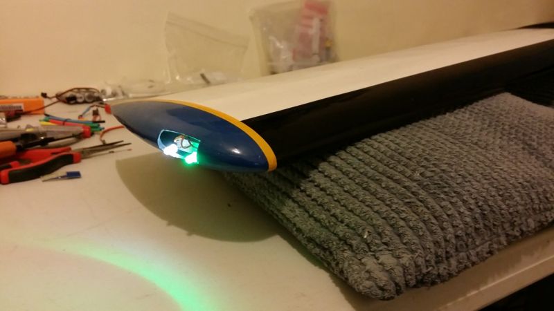
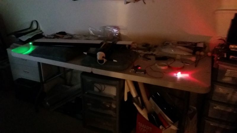
Anyway, I have cut into the Otter's wing tips and found they are hollow GRP which may have been of great help. LED modules made up and now sit in the cutouts. Now to find some clear plastic to make up lamp holder/hatch.
Replied by Phil Ford on topic Aero Navigation Lights
JRI wrote: as it will dissipate spikes and noise
Thanks John. I'll see if reconnecting pin 9 has any effect again because I believe I had tried using it before but something did not work right. But there may have been and probably was an error on my part. The circuit has been soaked tested for quite a few hours with no problems.
Back on Rainy Days project.
Spikes and noise could and do cause problems everywhere but is suppressed usually without you even knowing it was going on. Somewhere in your receiver or modules too and especially ESCs.I should have renamed this thread because it is incorrectly named Should read "Aircraft Position Lights".
That is the correct term I believe. Could be very handy on the usual grey dull days of Cashmoor. Would look great on some jets too......... :whistle:Anyway, I have cut into the Otter's wing tips and found they are hollow GRP which may have been of great help. LED modules made up and now sit in the cutouts. Now to find some clear plastic to make up lamp holder/hatch.
Last edit: 03 Feb 2017 10:08 by Phil Ford.
Please Log in or Create an account to join the conversation.
Moderators: DaveBright
Time to create page: 0.350 seconds
©
2009 - 2026
WMAC PCF Design