- Posts: 3156
- Thank you received: 903

Aero Navigation Lights
- Phil Ford
-
 Topic Author
- Offline
- Moderator
-

Less
More
23 Jan 2017 19:36 - 23 Jan 2017 20:04 #11681
by Phil Ford
Strangely enough I was looking through various projects that would be possibly helpful to RC fixed wing flyers and uncovered a project using digital pressure sensor for air speed (with temperature compensation), barometric altitude sensor. linked to a GPS sensor module and get the microprocessor to monitor yaw and pitch from a gyro and the data collected will show that the object was flying to slow, poor turning was causing a wing stall, angle of attack is wrong. All these modules and coding are around. :whistle: Then transmit this data to a ground station, maybe to a smart phone in your top pocket. However, each piece of data has to have a digitally recorded voice linked into the code.
I was thinking of a Jeremy Paxman type voice. So when the object appears to be flying "mushy" the system will alert the knob head on the sticks that he is near a stall, mushy or whatever.
Of course a system this good would ultimately say" Warning - mushy! Warning - mushy" and then take over control and regain a preset height and heading.
Or a cheaper version is to just flash a strobe on the aircraft when all is not well.
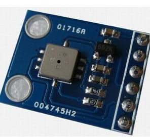
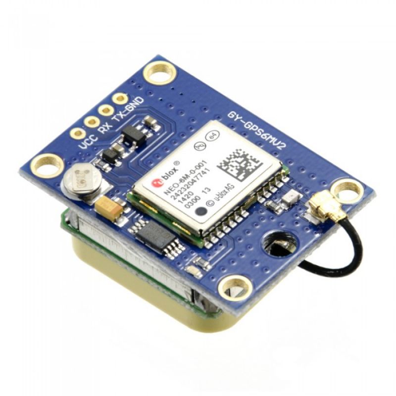
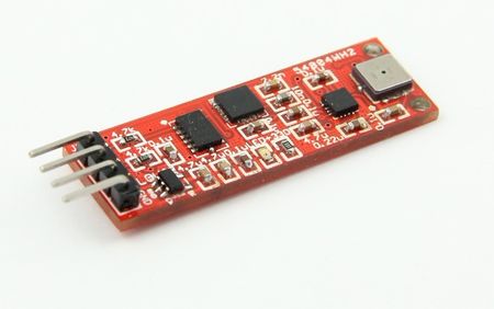
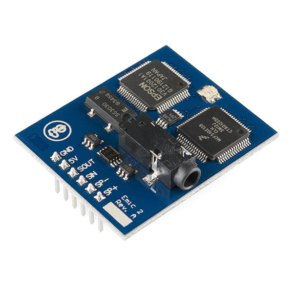
Images below are
1. pressure sensor 2. gps module (optional) 3. accelerometer/gyro module. 4. text to speech module
Replied by Phil Ford on topic Aero Navigation Lights
DavidTappin wrote: Phil, Peter Willis needs a talking mushy meter in his Tx for when his model is
maybe not talking, perhaps just some sort of warning light or buzzing sound would do the trick, could you make that your next project please?looking mushy in a turn
Strangely enough I was looking through various projects that would be possibly helpful to RC fixed wing flyers and uncovered a project using digital pressure sensor for air speed (with temperature compensation), barometric altitude sensor. linked to a GPS sensor module and get the microprocessor to monitor yaw and pitch from a gyro and the data collected will show that the object was flying to slow, poor turning was causing a wing stall, angle of attack is wrong. All these modules and coding are around. :whistle: Then transmit this data to a ground station, maybe to a smart phone in your top pocket. However, each piece of data has to have a digitally recorded voice linked into the code.
I was thinking of a Jeremy Paxman type voice. So when the object appears to be flying "mushy" the system will alert the knob head on the sticks that he is near a stall, mushy or whatever.
Of course a system this good would ultimately say" Warning - mushy! Warning - mushy" and then take over control and regain a preset height and heading.
Or a cheaper version is to just flash a strobe on the aircraft when all is not well.
Images below are
1. pressure sensor 2. gps module (optional) 3. accelerometer/gyro module. 4. text to speech module
Last edit: 23 Jan 2017 20:04 by Phil Ford.
Please Log in or Create an account to join the conversation.
- DavidTappin
-

- Offline
- Platinum Member
-

Less
More
- Posts: 549
- Thank you received: 164
23 Jan 2017 22:16 #11685
by DavidTappin
Replied by DavidTappin on topic Aero Navigation Lights
I thought for a moment that you were taking me seriously Phil. Until you mentioned a cheaper version with Jeremy Paxman flashing. Quite a surreal thought.
Please Log in or Create an account to join the conversation.
- Phil Ford
-
Topic Author
- Offline
- Moderator
-
Less
More
- Posts: 3156
- Thank you received: 903
23 Jan 2017 22:55 #11692
by Phil Ford
Replied by Phil Ford on topic Aero Navigation Lights
Seriously? Of course not David. But what you were suggesting is possible for under £100 :lol: Plus hours and hours of coding. ") Well within Pete's means.
Well within Pete's means.
Well within Pete's means. Please Log in or Create an account to join the conversation.
- Phil Ford
-
Topic Author
- Offline
- Moderator
-
Less
More
- Posts: 3156
- Thank you received: 903
25 Jan 2017 13:59 #11721
by Phil Ford
Replied by Phil Ford on topic Aero Navigation Lights
Cold weather keeps me indoors and wimping off to going out. So this next post is not really Aero Nav Lights but could be an idea for future project, building banks leds into the leading edge of something. Purchased a ready made pcb and modified some of the components and tracks. The chip is a PIC controller to trigger the logical MosFets, although any microprocessor could do it with a trigger voltage of 3.3 to 5v. The 5050 leds are so bright the camera could not handle the 6500mcd. All cobbled together for a test.
I''ll be glad to get out and do RC Aero on stuff in the cold hangar.
So this next post is not really Aero Nav Lights but could be an idea for future project, building banks leds into the leading edge of something. Purchased a ready made pcb and modified some of the components and tracks. The chip is a PIC controller to trigger the logical MosFets, although any microprocessor could do it with a trigger voltage of 3.3 to 5v. The 5050 leds are so bright the camera could not handle the 6500mcd. All cobbled together for a test.I''ll be glad to get out and do RC Aero on stuff in the cold hangar.
Please Log in or Create an account to join the conversation.
- Phil Ford
-
Topic Author
- Offline
- Moderator
-
Less
More
- Posts: 3156
- Thank you received: 903
27 Jan 2017 13:01 - 27 Jan 2017 13:02 #11730
by Phil Ford
Replied by Phil Ford on topic Aero Navigation Lights
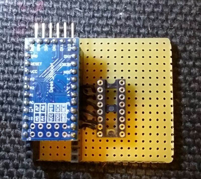
Right - Back to Navigation lights....... Made up a board with headers making the processor plug in (easier to update software). The outputs are sent to the Darlington array which can handle higher currents which in turn powers the LEDs. Image 1. This board would be okay for a plane which has 5.5 - 6.6v available with small leds.
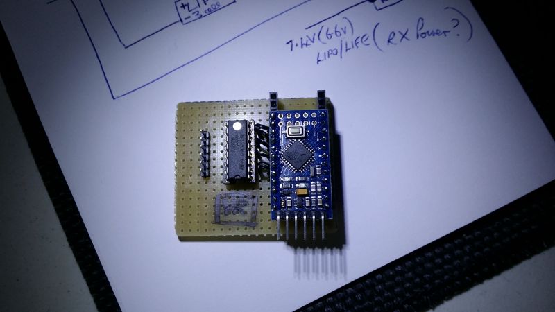
Image 2. This 12 volt board can be powered by a 3 cell lipo (or tap off three pins from the balance ports of main power pack) but because the voltage could be above 12 volts on a fully charged Lipo then a regulator is required. Note the blank space made for it. (Regulator did not arrive today ) The board is approx 50 mm square. This one is destined for the Twin Otter. The landing lights already fitted are 20,000mcd.
If this works in practice then I may etch a proper circuit board for future uses or if a member want a decent system.
The software is set as : Navigation Lights On when receiver is switched on and TX signal good. Gear switch turns on landing lights. If receiver loses power or signal then ALL lights come on. :ohmy:
Made up a board with headers making the processor plug in (easier to update software). The outputs are sent to the Darlington array which can handle higher currents which in turn powers the LEDs. Image 1. This board would be okay for a plane which has 5.5 - 6.6v available with small leds.Image 2. This 12 volt board can be powered by a 3 cell lipo (or tap off three pins from the balance ports of main power pack) but because the voltage could be above 12 volts on a fully charged Lipo then a regulator is required. Note the blank space made for it. (Regulator did not arrive today
) The board is approx 50 mm square. This one is destined for the Twin Otter. The landing lights already fitted are 20,000mcd.If this works in practice then I may etch a proper circuit board for future uses or if a member want a decent system.
The software is set as : Navigation Lights On when receiver is switched on and TX signal good. Gear switch turns on landing lights. If receiver loses power or signal then ALL lights come on. :ohmy:
Last edit: 27 Jan 2017 13:02 by Phil Ford.
Please Log in or Create an account to join the conversation.
- Phil Ford
-
Topic Author
- Offline
- Moderator
-
Less
More
- Posts: 3156
- Thank you received: 903
31 Jan 2017 17:10 #11793
by Phil Ford
Replied by Phil Ford on topic Aero Navigation Lights
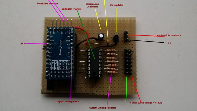
Regulator and transients filters now soldered in. Module tested and working great. (It does now after a few hours of scratching head and multimeter checking - left out one link. Doh! ) The board is powered from either a 7.4v lipo or 6.6 v Life. The processor gets 5 volt regulated and the Darlington Array handles any voltage up to 40 volt on it's output pins but in my module designed to use input voltage, 6.6 - 7.4v. All plugs and sockets are JST -SH type so standard servo leads can be utilised. However, I am making up my own leads.
Now that's done I can start the arduous task of fitting and wiring leds into the plane..
) The board is powered from either a 7.4v lipo or 6.6 v Life. The processor gets 5 volt regulated and the Darlington Array handles any voltage up to 40 volt on it's output pins but in my module designed to use input voltage, 6.6 - 7.4v. All plugs and sockets are JST -SH type so standard servo leads can be utilised. However, I am making up my own leads.Now that's done I can start the arduous task of fitting and wiring leds into the plane..
Please Log in or Create an account to join the conversation.
- JRI
-
- Offline
- Platinum Member
-
Less
More
- Posts: 502
- Thank you received: 108
31 Jan 2017 21:26 #11798
by JRI
Replied by JRI on topic Aero Navigation Lights
That 5V reg looks tiny Phil, have you tested how hot it gets under full load (or is full load the processor only?)
Please Log in or Create an account to join the conversation.
- Phil Ford
-
Topic Author
- Offline
- Moderator
-
Less
More
- Posts: 3156
- Thank you received: 903
31 Jan 2017 21:41 #11801
by Phil Ford
Replied by Phil Ford on topic Aero Navigation Lights
John, it's a 100 ma regulator which only has to power processor. The processor can take 40 ma max per pin, normally 20 ma but the board can only handle 200 ma maxed out. Hence the Darlington. The Array can handle 500 ma per pin max.
Mind you I could've used MosFets but don't need 10 amps per channel unless I was using car headlight bulbs for lights.. :lol:
Mind you I could've used MosFets but don't need 10 amps per channel unless I was using car headlight bulbs for lights.. :lol:
Please Log in or Create an account to join the conversation.
- DaveBright
-

- Offline
- Moderator
-
Less
More
- Posts: 886
- Thank you received: 129
01 Feb 2017 07:43 #11803
by DaveBright
Replied by DaveBright on topic Aero Navigation Lights
'The Darlington array' sounds cool.
Please Log in or Create an account to join the conversation.
- Brian
-

- New Member
-

Less
More
- Thank you received: 0
01 Feb 2017 08:41 #11804
by Brian
Replied by Brian on topic Aero Navigation Lights
I thought the Darlington Array was a film by Steven Spielberg
Please Log in or Create an account to join the conversation.
Moderators: DaveBright
Time to create page: 0.476 seconds
©
2009 - 2026
WMAC PCF Design