- Posts: 171
- Thank you received: 153

Pilatus PT6 Turbo Porter - Renovation
- throttletothewall
-
 Topic Author
- Offline
- Senior Member
-

Less
More
7 years 7 months ago #15912
by throttletothewall
Replied by throttletothewall on topic Pilatus PT6 Turbo Porter - Renovation
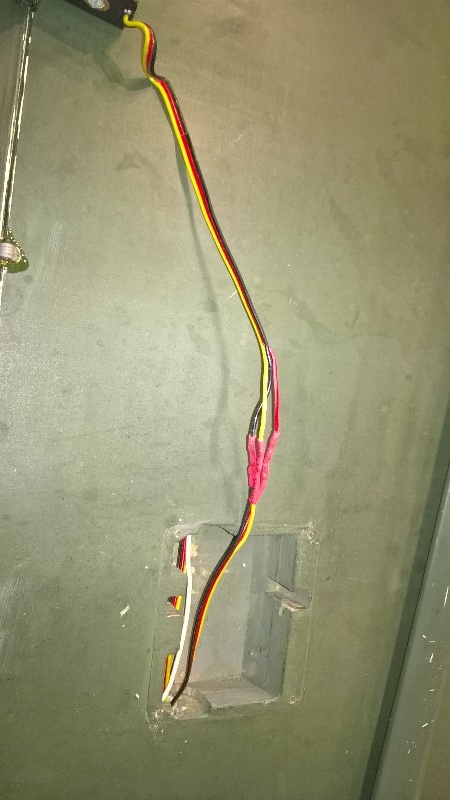
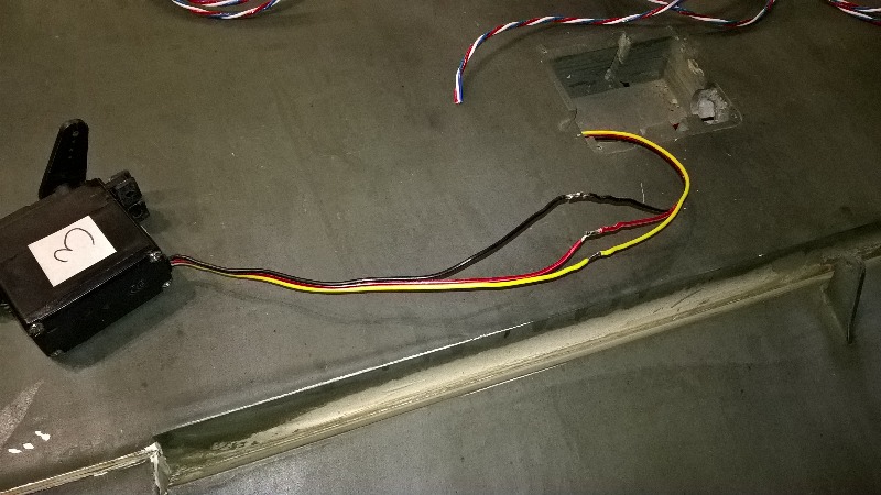
A week or two ago I also removed all the servos from the wings and discovered that they had all been hard wired. I am not a fan of this as it makes swapping out a failed or questionable servo a real pain. I have therefore reinstalled plugs on the servo wires and made up the new looms (using the Powerbox leads I had previously purchased) and put sockets on the wing half of the loom to plug the new servos plugs into and then put keepers over them for security. I also made up the new looms for the receiver end and then using all the new looms tested all the reinstalled servos and new looms using a servo tester to check that they all worked and all the colour coded heatshrink tubing I had used to identify which lead went to which servo had all been correctly fitted.

Please Log in or Create an account to join the conversation.
- throttletothewall
-
Topic Author
- Offline
- Senior Member
-
Less
More
- Posts: 171
- Thank you received: 153
7 years 7 months ago #15913
by throttletothewall
Replied by throttletothewall on topic Pilatus PT6 Turbo Porter - Renovation
Earlier this week I re installed the Rx NiMh batteries but placed them outside the engine mounting box to aid airflow into the turbine engine. The battery for the lighting was carefully fitted inside the box but well clear of all airflow holes. New Extension cables were made up for the batteries and carefully secured through the engine control bay and the front part of the cockpit to prevent any movement of plug/socket joints which had also been taped up to reduce risk of disconnect. I moved the engine Lipo into the engine control bay as I will need to remove this for charging and disconnect it at the end of each flying session to avoid deep discharge as the ECU draws a few milliamps even when the radio is switched off. To aid this regular activity I have changed the hatch to the engine control bay from a 8 screw fixing to two canopy latches to make removing much easier (and no screws to loose each time!!

Please Log in or Create an account to join the conversation.
- throttletothewall
-
Topic Author
- Offline
- Senior Member
-
Less
More
- Posts: 171
- Thank you received: 153
7 years 7 months ago #15914
by throttletothewall
Replied by throttletothewall on topic Pilatus PT6 Turbo Porter - Renovation
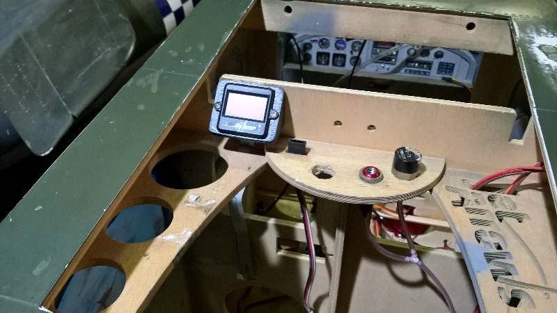
The pilot seats had been glued to the 'removable' floor to the cockpit but when I had tried to remove the floor the seats/pilots/floor could not be removed whilst the seats were still glued in place. As I am going to be installing the iTrap and some of the fuel tubing/cabling below this floor I need to make the pilots/seats easily removable but there is not easy access to fit/remove several screws to achieve this. So I devised a tongue and box system on the front and outer side of each seat and then just one screw for each seat in the centre to hold them all in place . this means both seats and the floor can be removed by taking out just three screws, all of which are easily accessible from the top hatch.


The following user(s) said Thank You: kevinross
Please Log in or Create an account to join the conversation.
- throttletothewall
-
Topic Author
- Offline
- Senior Member
-
Less
More
- Posts: 171
- Thank you received: 153
7 years 7 months ago #15915
by throttletothewall
Replied by throttletothewall on topic Pilatus PT6 Turbo Porter - Renovation
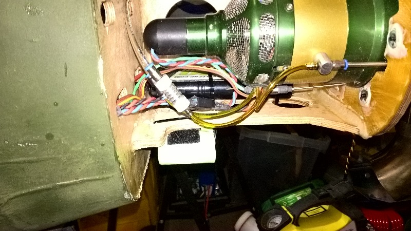
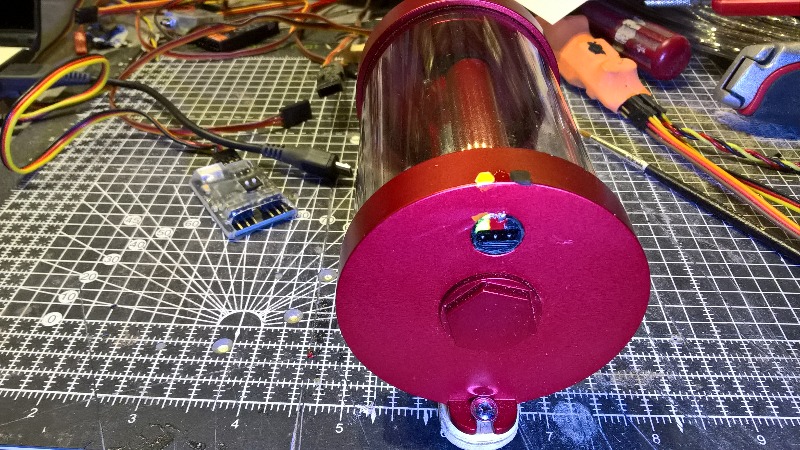
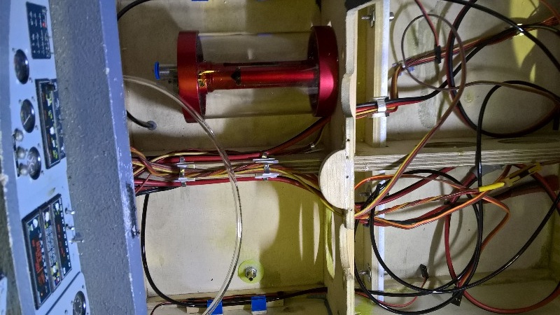
Today I have been aligning and securing all the wiring, air tubing and fuel tubing that passes under the cockpit floor and arranging the lighting controller, air valves and iTrap telemetry electronics on the Powerbox plate that sits above the main tanks. I have also made up the mounting plate and fixed the iTrap to the floor under the cockpit. I checked the iTrap instructions as the socket for the telemetry electronics does not have any plug polarisation so I knew that sooner or later the plug would be put in the wrong way round, given that it is going to be quite deep down in the cockpit and access for the plug is through a small hole cut in a former. So I painted some colour coding on the socket and the top edge of the iTrap to make sure that I do not make that mistake if undertaking some maintenance several months/years down the line.

The following user(s) said Thank You: kevinross
Please Log in or Create an account to join the conversation.
- throttletothewall
-
Topic Author
- Offline
- Senior Member
-
Less
More
- Posts: 171
- Thank you received: 153
7 years 6 months ago #16003
by throttletothewall
Replied by throttletothewall on topic Pilatus PT6 Turbo Porter - Renovation
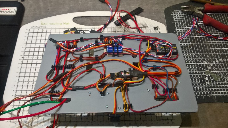
Well has been quite a week, I have spent three days mounting as much of the electronics that I can on the removable radio tray.
My logic is that I want to do as much of the commissioning and setting up as possible out of the model . I know there will be lots of plugging in and unplugging of servo plugs etc. as I connect everything up and set up the failsafe, giro, output mapping, failsafe, Rx redundancy, brake valves and lighting.This has already proved a correct logic, more of that later.
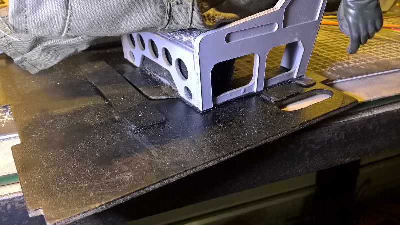
Wherever possible I have made little mounting plates for Satellite Rxs and telemetry electronics etc. I do not want to use double sided tape or Velcro to mount these but I do want them to be securely mounted. By using the mounts with a thin layer of rubber seal on top the electronics can be securely mounted using tie wraps and they are easily removable if required.
There has been lots of head scratching about the best place to mount various items and the board has been gradually built up through the week. See pic sequence.
My logic is that I want to do as much of the commissioning and setting up as possible out of the model . I know there will be lots of plugging in and unplugging of servo plugs etc. as I connect everything up and set up the failsafe, giro, output mapping, failsafe, Rx redundancy, brake valves and lighting.This has already proved a correct logic, more of that later.
Wherever possible I have made little mounting plates for Satellite Rxs and telemetry electronics etc. I do not want to use double sided tape or Velcro to mount these but I do want them to be securely mounted. By using the mounts with a thin layer of rubber seal on top the electronics can be securely mounted using tie wraps and they are easily removable if required.
There has been lots of head scratching about the best place to mount various items and the board has been gradually built up through the week. See pic sequence.


Please Log in or Create an account to join the conversation.
- throttletothewall
-
Topic Author
- Offline
- Senior Member
-
Less
More
- Posts: 171
- Thank you received: 153
7 years 6 months ago #16004
by throttletothewall
Replied by throttletothewall on topic Pilatus PT6 Turbo Porter - Renovation
I have spent the last two days trying to get the three Tx RF modules - 2 x 2.4Ghz + 1 x 900Mhz talking to the various Rxs and then getting the Rxs to talk to the Powerbox Rx inputs. THIS HAS NOT BEEN EASY!!!!
The first problem was that the Powerbox instructions did not tell me what the plug orientation was for the Rx input (The servo outputs had the little JR corner pieces to orientate the plugs but the Rx & tele sockets did not). I eventually found something online on one of the forums to resolved this, I didn’t want to blow a rather expensive Powerbox by getting plugs in the wrong way round before I had even started the setup!
I have had to change the outputs of the Satellite Rxs to a sort of serial output called UDi so that all channels can pass into the Powerbox, I also had to set the Powerbox up to read UDi at the input. The main 2.4Ghz Satellite Rx plugs into the Rx1 input of the Powerbox and I got that working, eventually, to drive a servo on channel 1. I then got the other two Rxs set up and plugged them in one at a time to the Rx2 input to the Powerbox. The 2.4 Ghz satellite worked fine and unplugging one or the other did not cause the signal to be lost and the Tx telemetry told me that it had gone to backup Rx, great!
However, the 900Mhz Satellite Rx needed output pins remapping to get it to work. Easy when you know how but again hours on forums and wading through manuals to find the right information. Then the problems really started, as the Powerbox only has two Rx inputs the second 2.4 Ghz Rx and the 900Mhz Rx have to be combined via a unit called an Enlink2. This unit is designed to let two separate Rxs (and power supplies) drive one servo and can combine two Rx signals on the basis of the best signal (failsafe has to be turned off on the Rxs to ensure the output goes null if the signal fails. (Failsafe is set up in the Powerbox but needs a null input to understand that the signal has been lost on all the Rxs)
Anyway to cut a long story short I have still not got this working but believe I have at last identified the problem after many hours on forums. The Enlink2 comes with two different versions of firmware, one to drive a servo (the standard retailed version of Enlink2) and another version of the software to combine PPM/UDI/serial signals. This will mean I have to download and flash the PPM firmware into the Enlink2 to get the UDi signals through to the Powerbox. I now await the USB adaptor to try and do this. So Watch this Space!!!


Please Log in or Create an account to join the conversation.
Moderators: DaveBright
Time to create page: 0.304 seconds
Latest Posts
-
-

- Various Gliders from Dave Ambrose ex W.M.A.C Membe...
- In WimborneMac Members / For Sale - Exchange - Wanted
- by 4Pedalsfly
- 1 week 1 day ago
-
-
-

- Ray Ivey's Models
- In WimborneMac Members / For Sale - Exchange - Wanted
- by Phil Ford
- 2 weeks 12 hours ago
-
©
2009 - 2025
WMAC PCF Design