- Posts: 1045
- Thank you received: 415

3D Printing
- Brian
-
 Topic Author
- Offline
- Platinum Member
-

Less
More
6 years 2 months ago - 6 years 2 months ago #20633
by Brian
Replied by Brian on topic 3D Printing
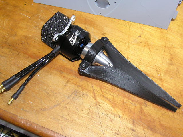
The prop blades needed to have their leading edges tidied up, apart from that, A gentle sanding with 400 grit paper around the leading and trailing edges was all that was needed. The blades and hub have all the mounting holes printed in. The blades fitted snugly into the hub with no additional work at all. The blades are held in with M2.5 screws, The screws are a clearance fit in the blade and one arm of the hub. The other arm has an undersize hole which is perfect to allow the retaining screw to be screwed in. The design showed its American origin at this stage, the width over the hub's arms is 1/2" exactly. The motor is an Overlander 1100kV. My only criticism of the hub's design is that both arms have the "tapped" hole for the retaining screw on the same side. The fact that the screw heads are on the same side of the hub centre line will probably cause vibration. In any case I shall keep well away from the side of the model when running the motor.Perhaps I'll alter the arrangement and use studding and nuts instead of screws.

Last edit: 6 years 2 months ago by Brian.
Please Log in or Create an account to join the conversation.
- Brian
-
Topic Author
- Offline
- Platinum Member
-
Less
More
- Posts: 1045
- Thank you received: 415
6 years 2 months ago #20637
by Brian
Replied by Brian on topic 3D Printing
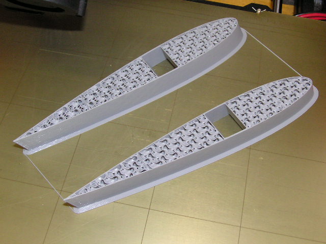
I was feeling quite pleased with myself, I'd transferred a couple more wing sections to be printed, and I hadn't referred to the prompt sheet. Good job I checked the print before it got too far. I had completely forgotten to alter the "infill" box from the default 15% to the new one, which is zero. As you can see from the photo, there's a lot of material doing nothing much but adding needless weight and stiffness to the section. I should have twigged it when the print time for these two sections was greater than the previous ones, which were a lot larger. Still, not to worry, all part of the learning curve.
Please Log in or Create an account to join the conversation.
- Brian
-
Topic Author
- Offline
- Platinum Member
-
Less
More
- Posts: 1045
- Thank you received: 415
6 years 1 month ago - 6 years 1 month ago #20650
by Brian
Replied by Brian on topic 3D Printing
My printer is a Prusa i3 Mk3, its about two years old, and a year or so ago, he model was upgraded from Mk3 to Mk3S. Prusa made a kit of parts available to existing Mk3 owners who wanted the extra versatility. Handy if you want to make 3D model aeroplanes. When my kit arrived, it consisted of all the hardware needed and a 300g spool of black PET-G filament. Having bought the kit, this unlocks the download from Prusa that enables the printer to print the parts needed for the upgrade.Pretty neat, a machine that makes its own new parts.
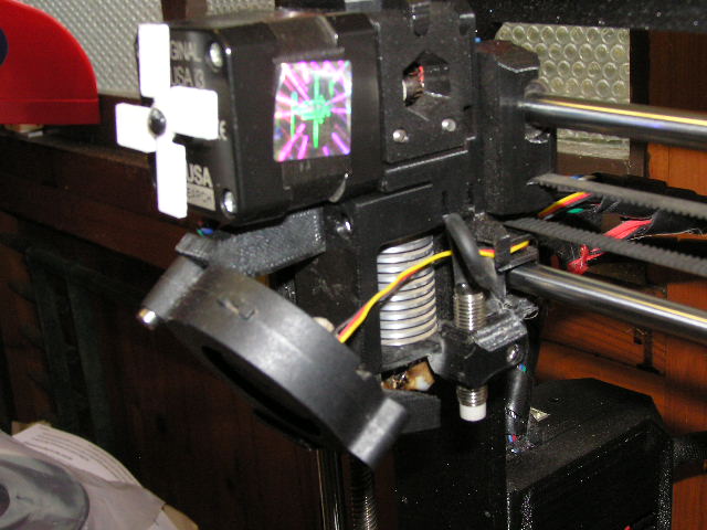
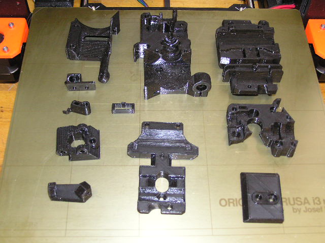
Photo ...904.JPG is the extruder, photo...905 is the upgraded parts. This all seemed easy, almost too easy to be true. It was! The parts in the photo might look OK, but in fact they were flawed. I found that the cause was the way that the filament had been wound on to the spool, it had a couple of places where the faulty winding had effectively trapped the filament on its way to the extruder. This meant that the printer kept printing, totally oblivious of the fact that it wasn't getting sufficient filament to do the job properly. Funny thing, the upgrade is, apart from any other features, to prevent the printer from running without the filament being correctly extruded. I took photos of the faulty spool and sent them to Prusa. In less than a week I received a completely new kit accompanied by a thank you note from their tech department. Most encouraging. When I've finished printing the present project, I'll get on with the upgraded again.
Photo ...904.JPG is the extruder, photo...905 is the upgraded parts. This all seemed easy, almost too easy to be true. It was! The parts in the photo might look OK, but in fact they were flawed. I found that the cause was the way that the filament had been wound on to the spool, it had a couple of places where the faulty winding had effectively trapped the filament on its way to the extruder. This meant that the printer kept printing, totally oblivious of the fact that it wasn't getting sufficient filament to do the job properly. Funny thing, the upgrade is, apart from any other features, to prevent the printer from running without the filament being correctly extruded. I took photos of the faulty spool and sent them to Prusa. In less than a week I received a completely new kit accompanied by a thank you note from their tech department. Most encouraging. When I've finished printing the present project, I'll get on with the upgraded again.
Last edit: 6 years 1 month ago by Brian.
The following user(s) said Thank You: 4Pedalsfly
Please Log in or Create an account to join the conversation.
-

- New Member
-

Less
More
- Thank you received: 0
6 years 1 month ago #20651
by
Replied by on topic 3D Printing
Looking good Brian.
Like yourself I printed all the upgrades for my printer, but now`s the time to upgrade my printer. so I will be selling my Ender 3 Pro with various filliments and bits and bobs as I am now joining the Resin printer collective. Just have a couple of more jobs to complete before I`ll let her go.
Like yourself I printed all the upgrades for my printer, but now`s the time to upgrade my printer. so I will be selling my Ender 3 Pro with various filliments and bits and bobs as I am now joining the Resin printer collective. Just have a couple of more jobs to complete before I`ll let her go.
Please Log in or Create an account to join the conversation.
- Brian
-
Topic Author
- Offline
- Platinum Member
-
Less
More
- Posts: 1045
- Thank you received: 415
6 years 1 month ago - 6 years 1 month ago #20652
by Brian
Replied by Brian on topic 3D Printing
That sounds interesting Alan, is the resin suitable for 3D printed R/C aeroplanes? I remember seeing a printer being demonstrated by Raymond Baxter on a BBC programme called "Tomorrow's World", that one used a UV laser and a UV cured resin. It was really crude when compared to the printers we can get now.
Last edit: 6 years 1 month ago by Brian.
Please Log in or Create an account to join the conversation.
- Brian
-
Topic Author
- Offline
- Platinum Member
-
Less
More
- Posts: 1045
- Thank you received: 415
6 years 1 month ago #20654
by Brian
Replied by Brian on topic 3D Printing
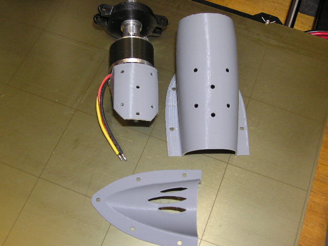
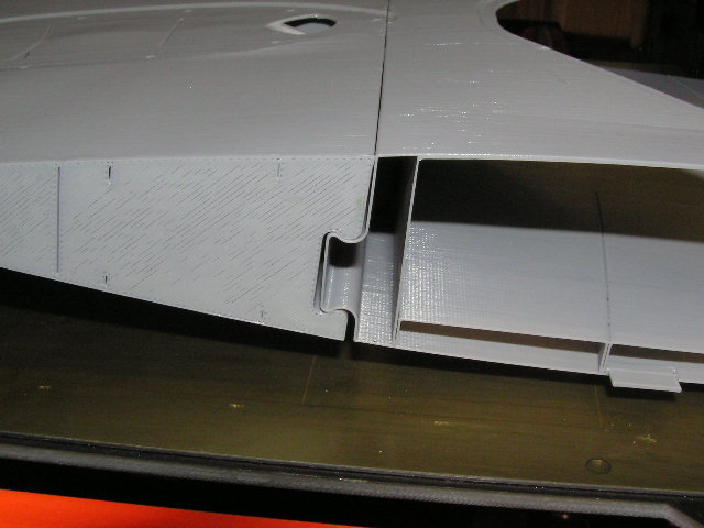
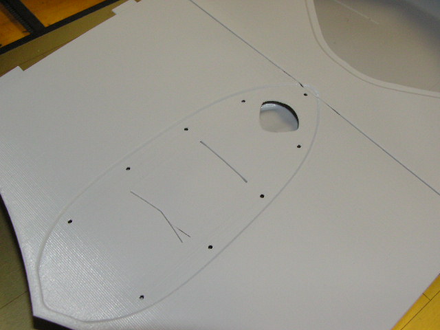
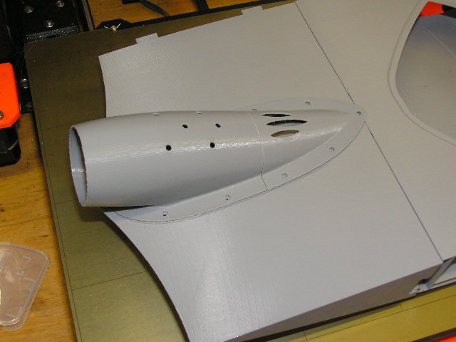
Considering the advances that have been made in computer aided design and manufacturing, I shouldn't keep being surprised when things fit together perfectly, joined by either glue or screws that go into holes that weren't made with a drill. The next few items of the Eclipson Blackwing will be assembled with a mix of glue and screws. I still think its pretty neat that the parts are usable straight off the printer. Seventy years ago I was a young aero-engineering apprentice, drilling and tapping the six holes in the motor mount and motor housing would have been a long and probably not particularly accurate process. Sometimes I feel a little guilty when I see how easy it is to make stuff that works first time every time, but its comforting to know that a part is being printed, even when I'm elsewhere, dutifully pushing SWMBO's goodie filled trolley to the car park
The photos are of the motor mount/ housing assembly, the "dovetail" spanwise joint between front and rear centre section, the recess in the top surface for the motor housing, note the moulded in hole for the motor wires. and finally the motor housing perched in place.
The photos are of the motor mount/ housing assembly, the "dovetail" spanwise joint between front and rear centre section, the recess in the top surface for the motor housing, note the moulded in hole for the motor wires. and finally the motor housing perched in place.
The following user(s) said Thank You: Phil Ford
Please Log in or Create an account to join the conversation.
Moderators: DaveBright
Time to create page: 0.457 seconds
Latest Posts
-
-
- Ray Ivey's Models
- In WimborneMac Members / For Sale - Exchange - Wanted
- by Brian
- 1 week 5 days ago
-
-
-

- Various Gliders from Dave Ambrose ex W.M.A.C Membe...
- In WimborneMac Members / For Sale - Exchange - Wanted
- by 4Pedalsfly
- 3 weeks 22 hours ago
-
©
2009 - 2025
WMAC PCF Design