
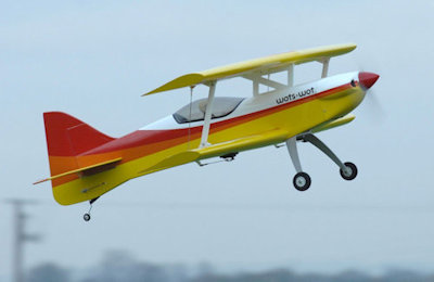
Designed by Chris Foss and sold by Ripmax this biplane has become a popular model in an instant. The first batch of models sold out quickly along with option packs. The second batch turned up but the option packs were in short supply. For me this put the purchase of the model on hold till the electric pack became available. This ARF comes as an airframe only, leaving the user to decide on the power option.
The power options of IC or electric come as a separate pack. Maybe to keep costs down but possibly they should've copied Hangar 9s idea of supplying the options within the kit. Let's get on with my review of this bipe that is designed to stay assembled and fit in the average family saloon.
The arf came in a quite reasonable size box and the contents were fairly well secured. Four wing sections, a fuselage, stabiliser and fin, landing gear/wheels, cowl, wing joiners, cabane, two wing struts, a decent spinner and the usual hardware bag. A glossy colour manual which is short on text but the idea is you follow the pictures. Not ideal for a newbie but okay for those with arf experience. The electric option pack I requested had been placed inside the main box for me. The pack has a battery mounting ply plate and slide off ply piece which your LiPo will be secured too. A magnetic hatch to cover the fuselage underside after your have cut out a section on the underside. 4 x Motor stand-offs. Directions on how to do this are also in the manual but not as simple as first glance. I will expand on that later.
Wings
Hinging of the control surfaces is done by CA hinges. They are pre-inserted into their respective positions but need to be verified before glueing with CA thin. Of the four wings in my kit only one wing needed some fiddling with to get the control surface close up to the trailing edge, it may have been slightly distorted because the outer edge does not quite line up perfectly with the wing edge, but the variation is very small. The other wings were perfect. Wing struts are located by handed plastic sockets that are glued into their respective positions found under the film covering.
Servo sockets are found under the film covering and are for stasndard size servos. I used Hitec 5485 MGs especially as these servos are going to have move two ailerons each. The bottom wing has the servos on the underside and a grp link connects the top wing aileron via a 2mm rod. This rod was replaced with 3mm carbon rod ending with 2mm adjustable clevis links.


Wing profile is quite thick with a large camber on the top edge. Wings are film covered but with sheeted leading edges. The bottom wing is joined by a laminated ply joiner which is tapered and has slight dihedral angle. The manual explains this so read carefully! It is imperative that it will slide equally into both wings before glueing with epoxy. I had to sand one side down to get the wings to butt together tightly at the roots. I opted to not glue my bottom wings together. Each wing has a ply peg at the forward edge of the root which locates into a slot in the fuselage. The rear of the wings are secured by nylon wing bolts. I opted for this idea to just in case, to enable reduced damage repairs.
The top wings are joined by an aluminium joiner tube. This tube slides through the cabane and then the wings are slid together and locked with two screws. This makes for the top wings to be removable if necessary. With only two servo leads to connect up, the wings are easily fitted, ensuring you guide the wing struts into their locations and the ailerons are then linked up and set up via the transmitter.
On trial fitting of the bottom wing I found that the contour of the wing's upper surface did not match that of the fuselage therefore changing the wing incidence. I rectified this by carefully skimming off the balsa fuselage edge on the bad side. So be aware!
A modification I did to help stiffen up wing mounting was to make up a a pair flying wires. These attach to the top of the cabane strut at centre (which also is C of G point) and the othe rend is connected at the bottom wing strut fittings. This is in case of wing side forces, ie; cartwheeling after a bad landing or being knocked over. Another member's Wots Wot was knocked over and sustained a split cabane strut.
Fuselage
Fuselage is solid due to lot's of balsa sheeting. The grp cowling was a very good fit and well painted. Landing gear is a curved aluminium strip secured by two bolts into the fuselage. This I felt was not good enough for a model of this size so I repaced the captured nuts with four 4mm spike nuts and bolts, drilling out the landing gear to suit. I may replace the gear at a later date with a more forgiving carbon affair. The wheels supplied were foam tyred but as I use a grass field I replaced these with slightly larger wheels to help avoid nose-overs.
Fitting of the cabane strut is a simple affair. A slot is pre-cut under the film on the top side of the fuselage. Other than ensuring it sits down properly before gluing with epoxy, a non issue. However, just verify that the wing tube slides through neatly though. My hole was a bit too tight and ensure the cabane strut locates fully into the recesses in the wing roots.
Tail steering is accomplished with a simple bent wire item with a small foam wheel attached. The wire locates into the rudder for steering.


After cutting the film at the rear of the fuselage, the stabiliser and fin can be dry fitted to check alignment. The stabiliser is fitted and glued with the elevator joiner wire hanging loose. Don't forget this because once the stab is glued you will not be able to fit the joiner. My stabiliser fitted perfectly but I did take my time verifiying the measurements from the wingtips and fuselage centre line before securing with Thin Cyano. The Fin is secured in the same manner.
Elevators are hinged using CA hinges and Thin Cyano, the wing joiner is glued at the same time with epoxy. These fitted well and close up to the stabiliser, minimising any gap. Elevator control is affected by a servo mounted up forward in the fuselage servo tray. Rudder servo also locates here, the servo being slightly raised on ply to allow the arm to swing clear of the elevator servo. Elevator control is by a steel rod.
Rudder is hinged by CA hinges and is glued to the fin and at the same time the tail wheel wire is located and glued with epoxy. Rudder control is surprisngly for this model of the pull pull type ensuring good control. The kit supplies wires, crimps and the adjustable rudder horn but leaves it to you to find a suitable servo arm to match.


Cockpit canopy is clear plastic and a pilot is supplied. Wow!
For IC engine the fitting of the engine mounting to the firewall, the latter which is quite well built up is standard. Locating your chosen engine and securing to ensure prop drive hub is just a few millimetres forward of the cowling.
For electric it is not quite that simple. On the underside of the fuselage level with the firewall is some markings. Underneath the wood has been laser cut but not fully. Using a saw blade to remove this section. This will allow access to fit the battery mounting plate which sits at a 45 deg angle in the fuselage. It locates uppermost on to the previously glued in cabane strut. The bottom end glues to the fuselage. using a hardwood angled profile. I did not glue it in but added more angle profile so that I could screw locate from the firewall side enabling me access if needed to the forward compartment. See images. Also further down the underside of the fuselage is option to to cut out a hole for air flow for through cooling. Supplied in the electric kit is a hatch with four small magnets which matches up to a former also with matching magnets. THe former has to be glued on to the inside of the battery hatch cut out. To get it to fit you will have to nibble away at the angle profile on the inside of the firewall so it can locate correctly. A bit of a fiddly job but a "must do" job though!
Power and Electrics
The motor shown in the image gallery is a perfect fit with regards to prop drive hub and cowling clearance. it is a gT Grand Turbo 40 series. However, the motor I decided to use later was a Turnigy SKDrive 5045 660kv rated at 1410 watts.max current 60 amps Speed controller is a Hobbywing Platinum 80 amp, 25% more capacity of what would be expected current draw at WOT. Mounted to get full airflow on the motor stand-offs, insulated by foam rubber and secure by cable ties. The independent receiver pack, i used 4 cell Eneloop Pro pack, mounted on opposite side mainly to assist the Centre of Gravity. A heavy duty switch/charge point is mounted on the right side of the fuselage enabling onboard charging. The main LiPo pack only has to power the motor therefore giving me some redundancy if the ESC or motor pack burns out. For initial flights the Lipo pack used was borrowed from another model and was a 5 cell, 3300maH 25C. Five minutes of varying flight returned a pack 70% used. The motor is designed for 4 - 5 cell packs so using a 6 cell would be pointless. Also to fit a decent sized capacity 6 cell would require hacking away a lot of fuselage. However, I did try a 3000mah 6 cell which would have to be shoe-horned in each time and I personally think there is no substantial gain. The 5 cell pulls it vertical easily swinging on the 15 x 8 prop.
Flight Test
After a maiden flight test by Jon Tappin, it was deemed that the model may be a little nose heavy so later I moved the receiver pack of 120 gms to the other side of the firewall under the main battery pack. I have since flown it and centre of gravity has not changed much. Trimmed out though it flies level with the elevator a little up now. But this maybe due to main wing incidence that another Wots Wot owner /club member reported, as he had similar issues. Other than these small items it flies extremely well, ample power.
Another flight test with the dedicated Lipo pack of 4000maH 30C 5 cell. This pack weighs in at 525 gms, a 100 gms more than the previous battery. I was expecting it to be overly nose heavy but did not appear so, although after trimming for level flight at half throttle the elevator is still up a little. A few more flights and this should be ironed out. Still flies well and is quick at full stick.
* Subsequent flights a few days later, the model became twitchy on the elevator! An inspection found the bottom wing loose at the forward edge. This meant that the top wing was just holding the bottom wing in place, a tight turn could have resulted in total loss. Removing the wing confirmed my suspicions. The small wing root ply spigots had sheared off leaving the wing free to move up and down. I had always thought this design was poor and this proved it. To rectify this I glued in behind the flat faces of the wings where they butt up against the fuselage some strips of 5mm ply. Then drilled in the centre of each flat a 6mm hole and glued in dowell pegs. Carefully marked where these dowels contact the fuselage and drilled out. Wing is nice and secure now.
A little warning though. With lots of wing surface area you would expect this model to float in. Well, it doesn't. It will suddenly just drop like a brick and most likely bend the landing gear which at least absorbs of the impact. The model really needs to be under some power on landing approach. It took me a few hard landings to discover this fact. I also would recommend that if you fly off really rough terrain, then use nylon bolts, maybe two 6mm into 6mm spike nuts. At least a not so good landing will shear bolts rather than damaging fuselage or a bad nose-over/cartwheel.
My Conclusion
Price Band as of publishing date £134 - £144 GBP airframe. Option kits £20 GBP. Good value for the money. Solidly built, new batch seem to have solved covering film issues reported. I did not have to do much ironing of the film. Excellent entry to Bipe models. Bright and colourful livery. Quality spinner similar to Irvine.
UPDATE: Wots Wot ARF as of December 2024 retails at £249 but shop around to possibly save a few pounds.

Recommended Mods
- Four point landing gear fixings
- Larger wheels if used on grass
- Use independent receiver pack if electric option
- Keep battery tray removable

