- Posts: 3170
- Thank you received: 903
Morris Dancer build
- Phil Ford
-

- Offline
- Administrator
-

Less
More
11 months 3 weeks ago #26905
by Phil Ford
Replied by Phil Ford on topic Morris Dancer build
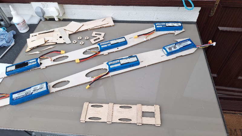
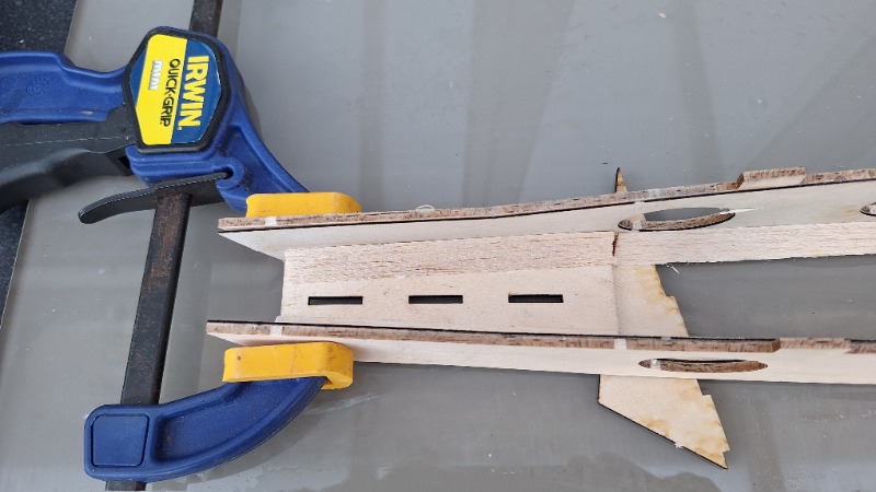
Take note of the slight error I made. The battery tray is notched to go just one way into the fuselage sides. Therefore make sure you glue the bracing tabs on the correct side. As I found out!
Please Log in or Create an account to join the conversation.
- Phil Ford
-

- Offline
- Administrator
-

Less
More
- Posts: 3170
- Thank you received: 903
11 months 2 weeks ago #26906
by Phil Ford
Replied by Phil Ford on topic Morris Dancer build
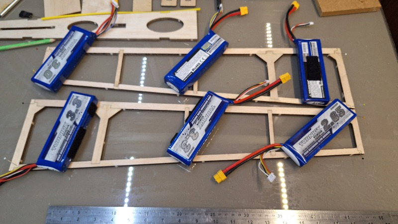
I started with the tail surfaces first. Dry fit, then glue n pin. Used lipos to keep flat whilst gluing the ply to the balsa (the balsa is on the outsides Kevin  )
)
Please Log in or Create an account to join the conversation.
- Phil Ford
-

- Offline
- Administrator
-

Less
More
- Posts: 3170
- Thank you received: 903
11 months 2 weeks ago - 11 months 2 weeks ago #26907
by Phil Ford
Replied by Phil Ford on topic Morris Dancer build
With the fuselage sides sorted I then inserted the battery tray after a few dry fits. I found
I had to apply a little chamfers on the tray tags to get the tray to slide into the fuselage sides. Once happy with the fit I fitted the F1 using epoxy and the lower bracing ply and the initial forward landing bear plate with Aliphatic. I will leave this area open for now so I can easily access the firewall if I decide to fit 3mm spike nuts to secure the motor. After a night of setting I then glued the tail skid plate. The fuselage is starting take shape.
I had to apply a little chamfers on the tray tags to get the tray to slide into the fuselage sides. Once happy with the fit I fitted the F1 using epoxy and the lower bracing ply and the initial forward landing bear plate with Aliphatic. I will leave this area open for now so I can easily access the firewall if I decide to fit 3mm spike nuts to secure the motor. After a night of setting I then glued the tail skid plate. The fuselage is starting take shape.
Last edit: 11 months 2 weeks ago by Phil Ford.
Please Log in or Create an account to join the conversation.
- kevinross
-
 Topic Author
- Offline
- Platinum Member
-

Less
More
- Posts: 1028
- Thank you received: 583
11 months 2 weeks ago #26908
by kevinross
Replied by kevinross on topic Morris Dancer build
After considering various covering solutions, have ordered solarfilm direct. (they still have considerable stock)
Works out cheaper due to less waste because one width of 67cm covers a single wing span
Works out cheaper due to less waste because one width of 67cm covers a single wing span
Please Log in or Create an account to join the conversation.
- Phil Ford
-

- Offline
- Administrator
-

Less
More
- Posts: 3170
- Thank you received: 903
11 months 2 weeks ago - 11 months 2 weeks ago #26909
by Phil Ford
Replied by Phil Ford on topic Morris Dancer build
My progress so far in rather small workspace - a utility room (No chance of doing it in the house)
Ailerons were assembled on the glass (originally a cooker splash back) and then spent some hours flying at Cashmoor whilst glue sets.
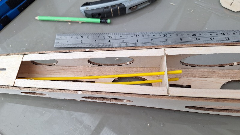
Next morning, a modification regarding the elevator control wires. Made up a 2mm ply former with two holes for the guide tubes 30 mm apart. Image shows dry fit.
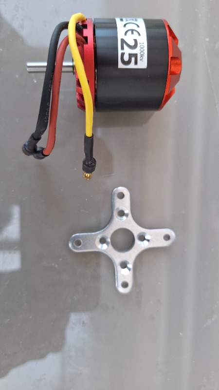
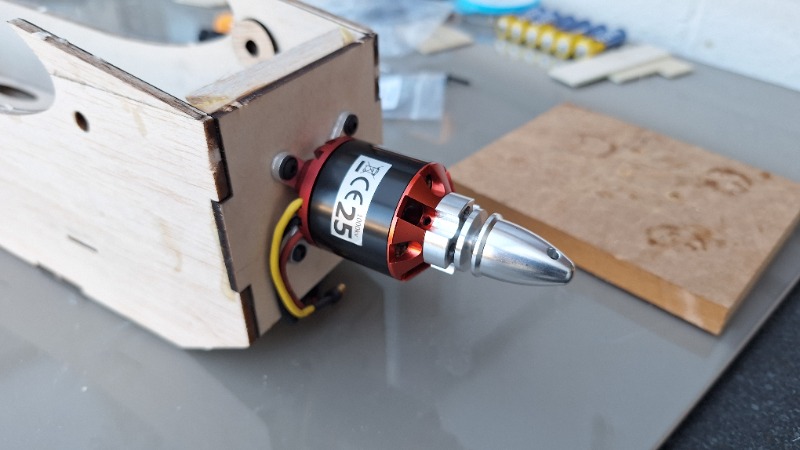
Having lots of motors but none suitable for this project I opted for the Ripmax Quantum II 25C 1000 kv. A light motor capable of 3 or 4 cells. The X plate mounting is a perfect fit to the kits laser cut holes in the firewall.
Last edit: 11 months 2 weeks ago by Phil Ford.
The following user(s) said Thank You: kevinross
Please Log in or Create an account to join the conversation.
- Phil Ford
-

- Offline
- Administrator
-

Less
More
- Posts: 3170
- Thank you received: 903
11 months 2 weeks ago - 11 months 2 weeks ago #26910
by Phil Ford
Replied by Phil Ford on topic Morris Dancer build
Until it is flown we won't know if the motor makes it "exciting enough" so may step up to the next size Quantum II 36 or 40. Although their X mounting plate requires 44mm distance between holes which may be right up against the tri-stock on the inside of the firewall. Worry about later if need be...
Last edit: 11 months 2 weeks ago by Phil Ford.
Please Log in or Create an account to join the conversation.
Moderators: DaveBright
Time to create page: 0.277 seconds
Latest Posts
- No posts to display.
©
2009 - 2026
WMAC PCF Design


