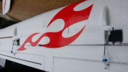
This 2 meter glider from Hobbyking has been around for some time and at the time of this article version 2 is still widely available. There are number of discussions on the two better known RC forums but to my frustration the threads go and on for umpteen pages and yet still no real information given. Some of it is guesswork, some posts ramble on about shipping, etc and making comments on the model even before they have it in their hands. So you have to trawl through the post in the hope of finding the information you require. This is not the case here. No debate but pure information.
Alternative as of end 2018 1600 version (Kit or ARF)
This Review has had an Update. Click here
So, rant over, the Phoenix 2000 glider comes in various configurations. kit form and plug-n-play. The kit version which will be covered here retailed at £40 GBP plus postage and was purchased from the UK warehouse of HK, extremely quickly I may add. Spend £54 GBP and get the PNP version requiring a receiver and lipo battery. The PNP or ARF model comes with a 2815 1050kv motor fitted with a 30 amp ESC. Prop size is 10 x 6. The folding prop spinner is red and made entirely of plastic. Personally I would recommend the kit version for longevity. Yes, it is really cheap but with a little effort can be a great model to fly.
Let's take a look at the kit version. All the items came well packaged and bagged. Hardware is also bagged up with numerous numbers of screws and bits-n-bobs. Mostly you need to scrabble through lots of little bags to find the screws that you think you need. Servo leads are supplied plus a Y lead for the optional flaps and associated hardware. The manual is barely basic, a few monochrome photos and what is worrying, the majority of the manual concentrates on control surface direction and TX set-up. If they think the user should need this then don't sell it to that user! Later I found that the recommended CG was spot on in my opinion. If you have assembled China models before you will know that the best policy is spread out all the bits, making sure it all looks possibly complete then screw together using the mode "common sense" or "that bit fits that bit". Honestly, it really is easy to put together the main airframe.
Specs (as per ARF version)
- Wingspan: 2 meters (78.74inch)
- Length: 1160mm
- Flying Weight: 980g
- Servos: 4 x 9g (Required)
- Motor: Brushless 2815/1050Kv
- (Required)ESC Included: 30A (Required)
- 6 channel RX
- 1300 -1800 maH Lipo
- Centre of gravity: 70mm from leading edge +-5mm
Fuselage
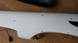
The blow molded fuselage is white and supposedly a composite material but is in fact a slippery plastic similar to milk bottle plastic. This type of plastic does not allow normal adhesives to stick, even [[velcro]] struggles and gives up after a period. So, to install items like the battery deck, wing securing plate and servo tray the manufacturers use small self tapping screws. This is not much of a downside because you can now remove these ply items and modify or repair to suit yourself.
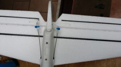
The stabilser and elevator are stiffened using carbon rod. The stabiliser and fin are a push fit together using a plastic molding and secured on the underside by another plastic item through which two long self tapping screws pull the items together The fin slides into the top slot and is secured by long 2mm screws and nuts, assuming you were supplied with them! Many users say they never got any either. So, delve into your junk box or do as I did and glue the fin in using UHU-POR and four 5mm screws. When screwing the tail items together just make sure you use two fairly long screws to ensure you have plenty of thread holding the bottom fitting to the stabilser/fin fitting up top.
The rudder hinge follows the usual foamy idea and I think this item was very weak, at least on my kit. I simply cut it carefully off, clean up the two surfaces, drilled out the holes by twisting a 3mm drill bit by hand and fitted small Robart 308 metal pin hinges, vaselined and glued in using UHU POR. Neat hinging and no binding! Note that this can done after the fitting of the stabiliser and fin.
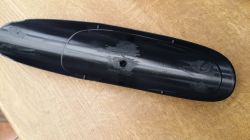
The canopy is black plastic which is a shame. If it were clear we could fit a pilot! The canopy is a blow molded item and is a push fit on to the fuselage. Along each side of the canopy are some little spikes which engage into holes in the side of the fuselage. I think this would be okay as long as you keep the canopy cool (ie; not laying in sunlight and getting soft and flexible) it may stay on. In fact on my maiden I used a small eleastic band just in case! It is smooth black but in the photo the inside is shown to highlight the little spikes.
Another little bit of advice - the fuselage is very slippery and will slide around while you are working on it, most annoying. I worked on the fuselage whilst it lay on an old blanket save me trying to follow it around!
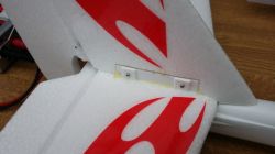
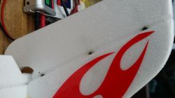
For a receiver I used an Hobbyking Orange 6 channel that I had laying around and is installed under the servo tray on a patch of velcro (hook and loop) For rear control surfaces I used Hitec 5055MG servos for the rudder and elevator. I love these digital micro servos, lots of torque and are programmable using the HItec HFP25 unit. I used the stock control rods and clevises. I may replace later if need be, but for now they will suffice. Many have said "clevises unlocked, nearly lost it". I suspect they did not secure them with tubing slid over them or in my case tiny cable ties. Come on Guys, basic stuff! The control horns are fitted using two screws used diagonally passing through pre-drilled holes (a time saver) into a nylon backplate. There is provision for using four screws but I did not see the need but there are plenty of screws supplied to do this. See images.
Power Train
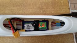
I initially used a NTM 2836 1000Kv 5T motor with a 4mm shaft. Fitting the motor was a tedious task especially for those of us with big hands. The glider designed for 28mm class brushless although in fact you could fit a 35mm if pushed but I don't think that would be necessary. In the kit you are given a plastic universal motor mount, yes you heard it right, a plastic universal motor mount and a thin metal (galvansied steel) plate. To install the motor you have slip the plastic mounting over your motor and leads and secure the motor to it. Then hold the two items up against the inside of the firewall trying at the same time to align the metal plate and using the 4 x 2mm machine screws to secure fix the motor to the fuselage. I fitted the ESC under the battery floor, which involved removing it, a 40 amp Turnigy Plush ESC which was slim enough to go under out of the way.
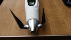
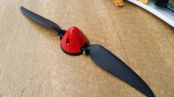
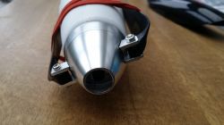
In the kit version you are supplied with a spinner, plastic with a red spinner cone and blades of 10 x 6. In desperation you could use this prop but I plumped for a 45mm aluminium spinner with cooling hole and branded 10 x 6 blades, costing £11.95. For power source I am using a Nano Tech 1500 maH Lipo 3 cell, 11.1v.
Note: This next item is not really so much of a review but gives you some pre-warning of issues with this model if not careful. With the fuselage secured and wearing safety glasses (always when test out new stuff) I gently powered up the motor taking it up to half throttle and reading the current and wattage. Now progressively up to full throttle. Far too much current and then a clicking noise. Power off!
THe NTM motor had got quite hot and had started to melt the plastic motor securing plastic thingy. Pulling the motor out of the fuselage my suspicions were correct. This is not a good way of mounting a motor especially in a plastic fuselage too. Obviously the 10 x 6 prop is too much for the NTM motor. Now we have a distorted motor mounting too.
After much number juggling I decided to forget the over-rated NTM and went for a Turnigy Aerodrive 2836 1040kv 12T (3.2 shaft) capable of 335 watts, 28 amps. I used the supplied X plate and the original metal plate drilled out to line up the mounting holes and refitted to the fuselage. Using the 10 x 6 blades now fitted to a 45mm spinner for 3.2mm shafts, a very smooth motor run up, and at WOT 315 watts and 26 amps. Motor just slightly warm which is to be expected as the model is not flying and pushing air over it. With that issue resolved time to assemble the wing and back to the review.
Turnigy Motor Specs
- Voltage: 2~3S Lipoly
- RPM/V: 1040kv
- Internal resistance: 0.075 Ohm
- Max Loading: 28AMax
- Power: 335W
- Shaft Dia: 3.175mm
- Bolt holes: 16mm & 19mmBolt thread: M3
- Weight: 80g
- Motor Leads: 3.5mm Bullet Connector
Assembling the Wing
Very straight forward assembly and you do have a couple of options to boot. You can keep the wings separate for easier transport or keep them locked together for a quick fit. However, I would suggest keeping the wings in one piece which saves unscrewing the wooden joiner underneath and unlocking the top plastic fittings each time. Invariably the screw holes will open up in no time at all.
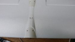
The two halves are joined by a plastic tube spar internally and on the underside a wooden strip of ply which sits into a recess and secured using four 10mm long screws. Already fitted at the roots are two plastic covers which when the wing is pushed together overlock the other root of the wing. These plastic covers also double up as the wing to fuselage fitting via four 3mm machine screws. The wing is supported by an internal spar rod, the ailerons are stiffened with carbon rods and the outer wing area with a ply insert.
Ailerons and flaps follow the common method of hinging in EPO foam. I feel there are two options here if you wish for security, run Blenderm tape along the hinge line or cut through and use small robart pin hinges. For ailerons and flaps I used Hitec HS65HB servos. These are nice mini servos with Karbonite gears and quite useful torque. These drop in neatly into the pre-molded servo positions. Plus even the flap places are both facing the same way which saves having to use a programmable servo to change direction or two channels mixed.
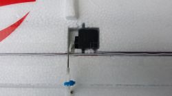
Control horns are fitted as per the tail surfaces. With aileron servos centered, arms fitted perpendicular and secured by the screw, the servos were glued into place with UHU POR. The control rods were then adjusted to length. In my case I found the rods too long so I had to cut off about 10mm and re-Z bend.
Flaps is easily set up. They are moulded into the wing and to bring them into use you just need to cut through the ends ensuring the flap can move freely without binding or snagging. Again drop two servos into their performed slots and link up. Just remember to set up your arms correctly for the flaps. I engage my arms so that at half flap the arms are perpendicular and at the full flap the servo has a bit more advantage of pull at the arm.
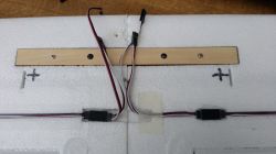
With all the servos checked it is a simple job of pushing your servo leads into the pre-cut slots and sealing down with either Blenderm tape or 25mm wide glass reinforced tape.
Two meters of wing should not be an issue for most family cars so keeping them in one piece is recommended as per my suggestion earlier. Slide the main spar rod into one wing, then slide the other wing up towards it and jsut before roor to root contact you have to slightly twist the wings to allow the plastic fittings to interlock. Turning the wing over take the wooden ply plate (optional is a dab of UHU POR) and fix it in it's recess using four screws from the hardware bag. I used four 10mm screws. Done!
Wing is secured to the fuselage by four 3mm machine screws albiet I was supplied with a set of spares.
First Flight
On maiden day the wind speed was around 10 - 14 mph and fairly steady. Raining but managed to get to the field during a break which in fact became just 10 minutes befor the weather closed in to very dismal and wet.
Initially using low rates on ailerons and high on elevator with about 30% expo on each rate. After a pre-flight check and range test I launched the Phoenix into the wind without using the motor to see how she flies. No issue at all. Glided forward staying fairly level and gently touched down 50 meters away. Now re-launch under power. With throttle stick pushed nearly to top the glider was trying pull away and with a fair amount of angle I pushed her upwards. I had to push in a quite a lot of down elevator to stop the Phoenix going vertical but easing off the power so folowed the easing of the elevator. Hum! A bit like my Dynamic S then, climbs swiftly under power on it's own.
After gaining some height of about 100 feet shut of throttle and the Phoenix levelled out nicely. That 300 watts of power pulls her up quite well and with authority. Now turned across the wind and see how it banks left and right, ailerons on low rates. Turning back into the wind I let it glide forward level for some distance and it stayed steady until stall speed, it appeared to just go all soggy with no obvious wing tip drop. Dropping the nose, she steadied again and I then applied throttle to climb back up.
Again it swiftly climbed at quite an angle so elevator had to be applied until the motor is turned off. Thrust angle issue similar to my Dynamic S. Performed the similar manouevres as per the first flight but using high rates now on ailerons. Not a big difference noticeable whilst gliding. Waht I wanted to check was the flap to elevator mix I had programmed in. I had set up the mix at 10% down for half flap (25 degrees down) and 20% for full flap which was 45 degrees down. Applied flaps in stages and virtually no ballooning up, but may take a few longer flights to dial in just the right amount. The main thing is it flies , flies well and does not have any bad habits at stall.
Thrust Angle to reduce the motor pulling up the model steeply would be easy in other types of aircraft but not so easy on this one due to the motor mounting. It is possible to insert some degree of down thrust by using some thin washers between the motor bracket and the firewall but I am a bit concerned that any loss of full contact between the X plate and the plastic firewall may start a split or tear in the fuselage material rendering the fuselage virtually useless. For me I'll stick to elevator compensation, maybe a mix dialled in?
With the centre of gravity at recommended 70mm, a Nano Tech 1500 30C, 3 cell, weight 125gms and the Turnigy motor weight 80gms plus the spinner /prop 25 gms the glider balances out nicely and all up weight of 985 gms.
Conclusion
The kit comes well packed and all the hardware and more is supplied. Although you may choose to junk some it and use bits you have to hand. EPO wing could have been better using compressed EPP as found on the EFX Racer from Durafly, really smooth and solid. Canopy may be an issue if the spikes get worn. Be careful of motor heat build up which could melt your firewall completely. The material used in the fuselage does not take to adhesives. 2 metre wingspan a nice size with regards to transport and visibility.
Fuselage will stay looking good for some time and if your into evening flying you could put some LEDS inside, the light showing through the skin. I only noticed this when I saw the receiver led glowing through one night. Don't forget to put coloured nav lights on the wing tips though!
Update: After some flight testing and a thrown prop blade which caused some issues with Turnigy motor I have since replaced the motor with an unbranded unit which came from the Durafly Dynamic S which has now been demoted to a slope soarer due to weakening fuselage. The motor is a 35mm of 920Kv. This motor has a 4mm shaft so laying around I had a 10x6 folding prop on a spinner ready to fit. Using the same 3 cell 1500maH Lipo the Phoenix now has about 240 watts at WOT which is ample to take it up to height. With three flights with this setup I am quite satisfied having a cool motor, lower current demands.


