
After many years of procrastinating I'm finally building a Phase 5. Designed in 1978 this model is often considered to be Chris Foss's (CF) best slope model. It was never available as a kit so the only way to get one is to build it yourself. CF is still selling the plans if you fancy one.
The Phase 5 plan calls for a built up wing but I'm deviating from the plan and making one from foam with a balsa skin. A snow day today meant I could make a start. CF does not specify what sections are used for the root or the tip so a bit of guesswork and internet trawling resulted in the semi-symmetrical E374 for the root, modified a little to make it thinner. The tip is fully symmetrical and is between NACA 0010 and 0011. It's actually 10.67% thick so maybe it's NACA 0010.67?
Images below show both left and right wing cores cut from the same block of foam, the semi-symmetrical root section and the symmetrical tip section.
The plan shows the root section and the tip section but does not specify what they are. Designed in 1978 (or earlier) I doubt that a computer was used to draw/create the sections and think that CF probably went for a couple of TLAR sections. Info from others on the net suggested that E374 and a symmetrical NACA section worked well on the Phase 5. I printed E374 at the correct chord length and it was too fat by a couple of mm. So I modified it to be the same thickness as the section on the plan and it matches very well. I'm convinced that my section will be aerodynamically superior to the original since there is some odd reflex going on on the plan because of the way he has built the flaps and ailerons from solid sheet carved/sanded to a triangular taper. That does not necessarily mean that mine will fly better, just that it will at least have a true section. At the tip I found that NACA 0010 was too thin and NACA 0011 too thick. So I modified the thickness and created NACA 0010.67.
If I had had a delivery of balsa today I could have made a start skinning those wings. Instead I took the opportunity to cut some more foam, this time the tailplane. The plan calls for a solid 3/8 balsa tail sanded to an aerofoil shape. Chris Wild (also planning to build a Phase 5) raised a concern that it would be difficult to carve/sand two identical halves. Whilst not impossible, it would certainly be a time consuming affair trying to make them and since I had some time on my hands I decided to try a technique that I'd not used before.
Cutting sharply tapered foam wings is possible with just one template if you anchor one end of the hot wire. Not only does it work, but it reduces the need to make a second template for the tip and the end results are a lot better than I could possible have made using my gravity cutter.
Images how the finished core, the root section, the tip section and the core placed over the plan.


Although originally planning on a sparless wing, it had been pointed out that the aileron and flap servo bays create a weak point and have decided to add a spar just in case. I tried cutting slots for the spar caps but could not get consistent results using the hot wire. So have decided to cut a vertical slice out of the wing and then rejoin it with a pre-made spar. I've gone for 1/4 x 3/16 caps and 3/16 balsa shear web which is drying overnight. See images below
I cut the wings in half and re-joined them with the spar in place. A light pass with the sanding block levelled them with the foam (protected with masking tape.
Then cut out the servo bays prior to sheeting. I'll keep the foam blocks and cut a slice to line the floor of the bays later. Then cut a slot for the servo wires.
A hard point has been added to the root of the wing. Once skinned I can drill through for the wing bolt.
Skins are 1/32 balsa secured using Gorilla (polyurethane) glue. Spread it thinly using an old credit card. I find it easier to use more glue than necessary then remove the excess. When spreading you need to move slow enough for a dam of glue to build up in front of the credit card. This ensures that the wood is wet all over. The edges and corners are particularly important.
Skinned cores are then placed back in the foam off-cuts and tapes all around to make sure the leading edges and trailing edges are tightly in place. Finally some weights are added to hold it tight until dry, overnight..
The wings came out of the skinning process and I've spent the last few days finishing off using aliphatic glue, so it takes a while between tasks.
A 1/4 inch leading edge and 1/16 hardwood trailing edge is added.
Ailerons and flaps are cut out and faced with 1/4 leading edge and 1/8 caps on each end. The wing trailing edge is also faced with 1/4
The servo bays are opened up and faced with 1/8. Wing tips added and waiting to be carved and sanded to shape. Wing root was sanded and ready for joining.


Wing is sanded and joined. Many kits used to tell you to join the wings using epoxy. This is messy and you have to work fast. I use aliphatic (yellow) glue. Gives you plenty of time to line things up and you can use masking tape to pull the two wings together for a tight and neat join. Phil, what does the P6 say for wing joining?
The joint is reinforced with a glass bandage. Again, in the past you would have been given a thick bandage that always gave you an unseemly ridge where it went from veneer to bandage. I've used several layers of thinner glass, each one getting a little wider - 20mm, 40mm, 60mm, 75mm and 90mm. You get a really strong joint this way as well as a fine edge. The widest layer goes on last to cover up any frayed edges underneath.
After a lot of procrastination I decided how to secure the flap and aileron servos. I'd initially saved the foam thinking I might use that for packing, but the wing is too skinny and ply and balsa are used instead.
Images show the servo attached to a 1/16 ply plate and hardwood blocks for the servo screws. A plate of ply and balsa is screwed to the servo plate and the balsa is sanded so that the servo ends up flush with the bottom surface of the wing.
For the flaps I used 4mm ply and 3mm balsa. Ailerons used 1/16 ply and 1/16 balsa due to the wing being thinner out there. The balsa/ply plate is then glued into the wing and later the servo plate can be screwed back in place.
The Fuselage
First task is to make a bellcrank for the all moving tailplane. This is from 2mm G10 (yellow) with 1.5mm G10 (black) laminated to create a thick 'bearing' for the pivot. I've used much thicker piano wire than shown on the plan with a view to reducing that waggy tail that is so common on AMT's (All Moving Tail Once the crank is made a 1/16 ply box is constructed to house it all.
You'll remember from earlier in article that the tailplane had been cut from foam? Last night I skinned them with 1/32 balsa using Gorilla glue like I did for the wings. Today was time to face the leading edge with 1/4 balsa and the trailing edge with 1/16 x 1/16 spruce. The tips have a core of 1/16 ply and 1/8 balsa.
And I've made a start on the pockets for the tubes in the tail. A chunk of foam/balsa was cut out. The base is then lined with 3/32 at the front and 1/8 at the rear which seems to place the tubes about central in the slot. The sides are faced with 1/32 and scraps hold these sides in place while the glue dries.


The fuselage is a simple affair. A more modern design would use a lot less wood for lightness and to reduce costs. However, this model is going to be flown heavy in strong winds and using 1/2 inch blocks of balsa as designed will make it very strong.
The fuselage has just three formers, one in the nose, one in front of the wing and one behind the wing. The fuselage is built inverted over the plan. Fuselage sides have 1/8 x 3/8 spruce stringers along their upper surface and 3/8 triangular section balsa along the bottom surface.
The plan calls for a closed loop for the rudder control. But I'm not a fan of closed look and will be using a carbon rod in a PTFE tube. Holes were pre-drilled in the formers but I wanted another support along the tail boom. The trouble is that the elevator pushrod also has to move freely in that space so I could not put another former in there. It's also very tight and adding a support after sheeting was not going to be possible. So I've made a thick support of 1/2 inch balsa faced with 1/16 ply. A 3mm hole is drilled through and then a 5mm hole is part-drilled through the block. When the carbon rod and PTFE tube is passed through the two formers it naturally lines up with the 5mm guide hole to pass through the 3mm hole at the other side of the balsa block.


The all moving tail has ended up being rock solid. I don't know if it's due to using over-sized piano wire or if it's because I've developed better skills in the 10 years since the last AMT I did. Either way I'm happy. I used my pin boards to line up the AMT box vertically while I glued the tubes into the elevator halves lying flat on the boards. I was just hoping that it would work...and using 5-minute epoxy you don't have long to get it right. Fortunately the tail ended up perfect and it lines up with the wing to within a fraction of a degree.
Lots of fiddly jobs doe over the last couple of days. The wing bolts and dowels are done. I opted to use rivnuts in the end because their extra height meant I couple still use short bolts and have the mounting plate lower in the fuselage where it had something substantial to bond to...the spruce longeron.
And apart from a final sanding, it's all complete!


Finishing the Phase 5
The advantage of an impromptu day off work means you can get a lot done so got the Phase 5 covered. The covering is waiting for some stickers to liven it up a little.


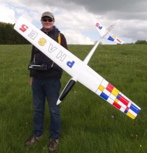
Maiden Flight Report
May 13th 2018 and a possible day for the maiden so after visiting a few slopes it was back to Win Green for the evening hoping that the wind would have picked up and swung NNW. It was stronger but still NW. I had a 15 minute flight with the Phase 5 and then drove east about 15 minutes to another slope. Another true NW slope and here I was able to fly for a further 45 minutes until sunset, when it was getting cold.

