- Posts: 1045
- Thank you received: 415

Back to Basics
- Brian
-
 Topic Author
- Offline
- Platinum Member
-

Less
More
3 years 7 months ago - 3 years 7 months ago #25634
by Brian
Replied by Brian on topic Back to Basics
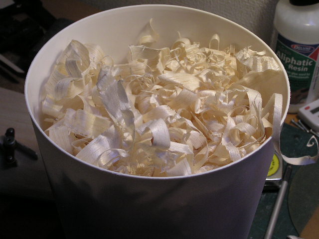
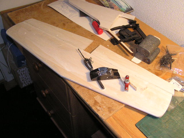
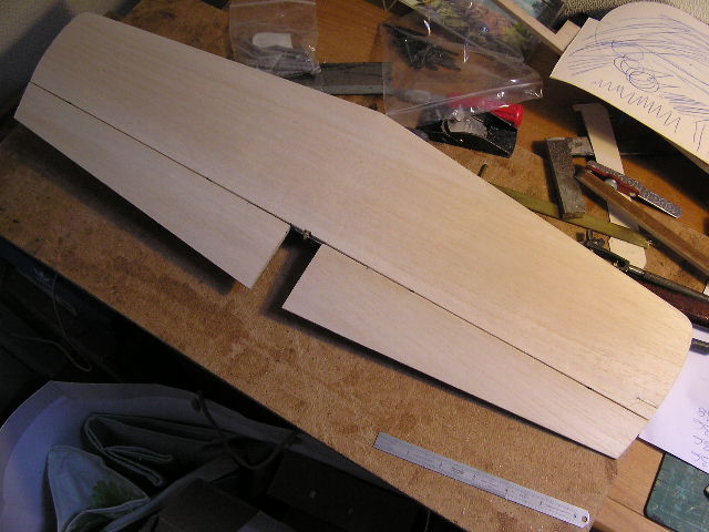
The tail plane and elevators are hinged, and a bit of shaping has been done with a plane. The elevators were slightly over length and had to be moved out spanwise to leave a gap between them for the fuselage. The tools are a pin vice, 3.1mm drill bit, Robart hinge drilling jig and (everybody should have one!) a Stanley No. 12-101 plane. Easy to use and set up and has a blade that can be sharpened on an oil stone. The initial shaping went much quicker than I thought, and I had a mug of tea as well. Fin and rudder next. The waste bin shows that the initial shaping has removed quite a lot of balsa, with remarkably little mess in the process.
I was almost at the point of abandoning the Airsail Chipmunk, I could not get the fuselage sections right. I stopped trying when I ran out of cornflake packet templates. I'd written to Sarik hHobbies on the off chance that they might sell me a non-standard Chipmunk package. After nearly two weeks they responded, and yes, they will supply enough laser cut parts for the fuselage, this cuts the costs by about 50%. With a bit of luck I'll be able to graft the existing flying surfaces onto the Sarik fuselage and have an Airsail/Sarik Chipmunk.
I was almost at the point of abandoning the Airsail Chipmunk, I could not get the fuselage sections right. I stopped trying when I ran out of cornflake packet templates. I'd written to Sarik hHobbies on the off chance that they might sell me a non-standard Chipmunk package. After nearly two weeks they responded, and yes, they will supply enough laser cut parts for the fuselage, this cuts the costs by about 50%. With a bit of luck I'll be able to graft the existing flying surfaces onto the Sarik fuselage and have an Airsail/Sarik Chipmunk.
Last edit: 3 years 7 months ago by Phil Ford.
The following user(s) said Thank You: 4Pedalsfly, kevinross
Please Log in or Create an account to join the conversation.
- Brian
-
Topic Author
- Offline
- Platinum Member
-
Less
More
- Posts: 1045
- Thank you received: 415
3 years 7 months ago - 3 years 7 months ago #25643
by Brian
Replied by Brian on topic Back to Basics
Today I started sanding the tail plane, elevators, fin and rudder. I wasn't until I sanded right through the fin sheeting that I realised that I hadn't really thought through the build sequence properly. The tail plane and fin structures are built from 1/4" thick "sticks", what I should have done is to sand the basic structure to give a slight taper towards the tips, taking it from 1/4" to 5/32" or even 1/8". It has been a dusty afternoon bringing the final shaping of Moonglow's tail bits. However, a brief instruction session from SWMBO had me operating the Dustbuster like a pro. And there doesn't seem to be any balsa dust about the place at the moment.
I spent a while going over the plan again, and looking at the laser cut parts that are left. The original plan shows the fin strake shaped from trailing edge section, my kit has a laser cut profile from 1/4" sheet, more work for the Stanley plane and sanding block! Laser cutting is of course very accurate, the downside is the scorched edges of the parts. Generally this isn't a problem, but Moonglow is to be covered in a transparent fabric, and any brown bits will show. One "brown bit" that'll be a problem is the joint between the front and rear fuselage sides. By the extent of the scorching it looks as though the laser cutter was getting pretty enthusiastic at that point. There is a considerable difference between the top and bottom of the sheets, its as though something on the underside is deflecting the cutting beam in all directions. The scorching really does take quite a lot of sanding to remove it. Still, on the good side, the model is getting lighter with every stroke of the sanding block.
I mentioned in a previous part of this build that I intend to cover the model with Diatex 1000. Sarik Hobbies sell a version of this material called Diacov 1000. I ordered some of that to see how it compared. Diatex 1000 is a finely woven pure white material, somewhere between silk and very light fibreglass fabric. Diacov 1000 is cream coloured, and pleasantly translucent. The piece I have seems heavy and rather stiff, must be OK as the LMA use it. We'll see.
Last edit: 3 years 7 months ago by Phil Ford.
The following user(s) said Thank You: 4Pedalsfly
Please Log in or Create an account to join the conversation.
- Brian
-
Topic Author
- Offline
- Platinum Member
-
Less
More
- Posts: 1045
- Thank you received: 415
3 years 7 months ago - 3 years 7 months ago #25645
by Brian
Replied by Brian on topic Back to Basics
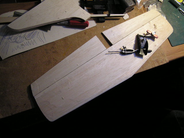
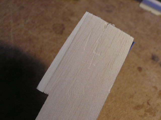
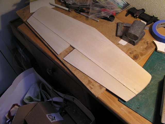
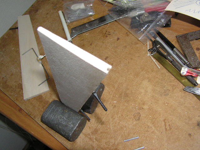
I woke up at four fifteen this morning, didn't want to read a book, instead I made tea, then suitably fortified I sanded the Moonglow's tail plane and elevators from the first sanding with coarse grit block to the second sanding. Finishing will be done with 120 grit paper on a block. The elevator outboard tips have been re-profiled to match the tail plane, and the elevator trailing edge thickness has been reduced to 1/16". When fitting the fin to the fuselage, there was a gap when the fin was seated onto the tail plane. second photo shows the infill pieces needed, shame the laser cutters didn't notice the actual shape shown on the plan. I re-read Mike Birch's build notes again this morning, he wrote about why he changed the airfoil section at the tip of the wing, simply to change the stall characteristics of the model. The change in section from root to tip ensures that the wing tips continue to give lift when the centre section is in a stalled state.
Since my early days with rubber models, I've been aware of the need for washout at the tips of wings, and I'm surprised that it doesn't seem to get a mention these days. Come to think about it, I never heard of the dreaded "Tip Stall" until a few years ago.
The first "real" stall I experienced was in a Harvard, nose up and reduced power caused a rumbling sound and quite a lot of vibration. That was the inner wing and root about to stall. Fortunately the wing tips were doing their designed task and the aircraft didn't drop a wing.
On the subject of washout, there are a couple of designs by Colin Usher. I think Chris Foss might find them a bit upsetting as both designs follow the lines of his AcroWot and ExraWot. The models are called Killerwatt and Megawatt. The reason I mention these models is that in Colin's build notes, there's the advice to build the wing upside down, with the trailing edge flat on the building board. This gives built in washout and improves stall performance. I suppose I could try the same method with Moonglow's wing?
Last edit: 3 years 7 months ago by Phil Ford.
The following user(s) said Thank You: 4Pedalsfly, kevinross
Please Log in or Create an account to join the conversation.
- Brian
-
Topic Author
- Offline
- Platinum Member
-
Less
More
- Posts: 1045
- Thank you received: 415
3 years 7 months ago #25654
by Brian
Replied by Brian on topic Back to Basics
After the early start, things deteriorated a bit. The elevator horn is brass soldered to the elevator joiner, the whole thing is inside the fuselage, giving a nice clean exterior appearance. I made the horn from a piece of brass strip, then went to silver solder it to the joiner. Snag. The flux had gone off. The plan said "solder", so that's what I did, with ordinary lead based solder and Fluxite paste. The joint looks OK. I'll hang a 1 Kg weight on it tomorrow just to make sure. I'm going to drill the elevators for brass tube that fits the joiner. Fix the tube to the elevators with cyano then fit the joiner to the tube with epoxy. That should prevent the joiner from loosening.
The following user(s) said Thank You: Phil Ford
Please Log in or Create an account to join the conversation.
- Brian
-
Topic Author
- Offline
- Platinum Member
-
Less
More
- Posts: 1045
- Thank you received: 415
3 years 7 months ago #25657
by Brian
Replied by Brian on topic Back to Basics
Haven't done the weight test on the elevator horn yet, I'll use a 1 Litre milk container, I seem to remember that a 1 Litre of water weighs 1Kg. The container won't be available until sometime tomorrow.
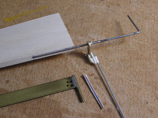
The elevators were marked out, checked and drilled for the joiner location tubes. A groove for the joiner wire was cut into the leading edge of the elevator with a tool made from scrap brass tube and a piece of flat brass strip. The brass strip is a bit of an overkill, but there's a reason for that. In order to not lose the thing, I keep it in my tool box, and its too big to get lost. Yesterday it provided the brass for the elevator horn. The brass tube is sharpened from the outside with a fine file. With the centre line of the groove marked out, its fairly easy to cut the groove by eye. The groove needs to be oversize to allow room for the epoxy resin that'll hold everything together on assembly.
The elevators were marked out, checked and drilled for the joiner location tubes. A groove for the joiner wire was cut into the leading edge of the elevator with a tool made from scrap brass tube and a piece of flat brass strip. The brass strip is a bit of an overkill, but there's a reason for that. In order to not lose the thing, I keep it in my tool box, and its too big to get lost. Yesterday it provided the brass for the elevator horn. The brass tube is sharpened from the outside with a fine file. With the centre line of the groove marked out, its fairly easy to cut the groove by eye. The groove needs to be oversize to allow room for the epoxy resin that'll hold everything together on assembly.
The following user(s) said Thank You: 4Pedalsfly, kevinross, Phil Ford
Please Log in or Create an account to join the conversation.
- Brian
-
Topic Author
- Offline
- Platinum Member
-
Less
More
- Posts: 1045
- Thank you received: 415
3 years 7 months ago #25664
by Brian
Replied by Brian on topic Back to Basics
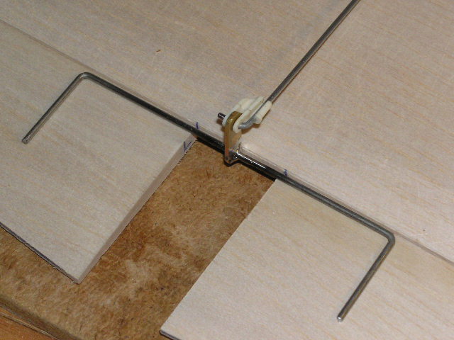
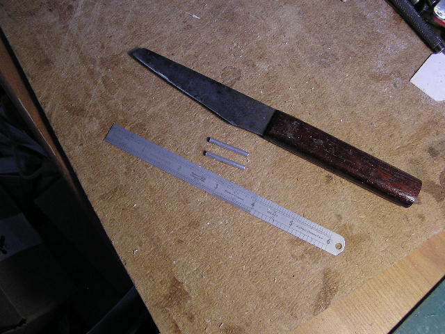
The holes for the joiner were drilled and the groove was cut in the second elevator. The "stress relieving" tubes were cut to length using an old leather workers knife. Don't know the make of the knife as the blade has no markings, but it holds its edge very well in spite of the things I do with it. I cut small bore tubes by rolling the tube on a flat surface with the blade pressed firmly on to the point where the tube is to be cut. Once there is a distinct line around the tube, hold the tube either side of the cut and a sharp bending action causes the tube to snap off cleanly. The tubes are slightly shorter than the legs of the joiner, and they are pressed in to a point slightly below the bottom of the joiner groove, this is to avoid jamming caused by the bend at the top of the leg. A shallow notch had to be cut in the centre of the trailing edge of the tail plane to allow free movement of the control horn. Next job is to chamfer the leading edges of the elevators, re-assemble them and adjust the joiner's legs to level the elevators.
The following user(s) said Thank You: 4Pedalsfly, kevinross
Please Log in or Create an account to join the conversation.
Moderators: DaveBright
Time to create page: 0.318 seconds
Latest Posts
-
-
- Ray Ivey's Models
- In WimborneMac Members / For Sale - Exchange - Wanted
- by Brian
- 3 days 10 hours ago
-
-
-

- Various Gliders from Dave Ambrose ex W.M.A.C Membe...
- In WimborneMac Members / For Sale - Exchange - Wanted
- by 4Pedalsfly
- 1 week 5 days ago
-
©
2009 - 2025
WMAC PCF Design